| CPC F16F 7/123 (2013.01) [E21B 19/02 (2013.01); F16F 2226/04 (2013.01); F16F 2230/0005 (2013.01); F16F 2230/0047 (2013.01); F16F 2232/08 (2013.01); F16F 2236/06 (2013.01)] | 11 Claims |
|
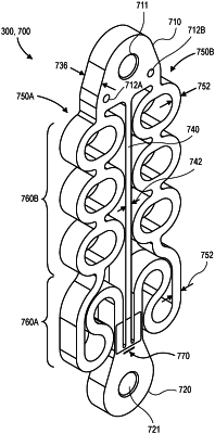
1. A damper, comprising:
an upper connector configured to be connected to a cable;
a lower connector configured to be connected to a load;
a cover positioned between the upper and lower connectors;
a body extending between and connecting together the upper and lower connectors, wherein the body is positioned at least partially within the cover, wherein the body permanently increases in length in response to a tensile load applied to the body by the cable and the load, and wherein the body comprises:
a first portion that is substantially straight and extends longitudinally between the upper connector and the lower connector; and
a second portion, wherein the first portion is configured to experience greater plastic strain than the second portion, wherein the second portion comprises two laterally offset portions, wherein the first portion is positioned at least partially between the two laterally offset portions, wherein each of the two laterally offset portions of the second portion comprises a plurality of continuous loops and a tortuous portion, wherein the tortuous portion comprises a plurality of turns extending in opposite upward and downward directions over a common distance between the upper connector and the lower connector, wherein the plurality of turns comprises first, second, and third turns over the common distance arranged laterally outward relative to a longitudinal axis of the damper, and wherein the body comprises a one-piece configuration having the first and second portions; and
a visual indicator that becomes visible once the body has increased in length, wherein the visual indicator is disposed on the body separate from the first and second portions.
|