| CPC F16C 11/0604 (2013.01) [F16C 11/0685 (2013.01); F16C 11/0695 (2013.01)] | 19 Claims |

|
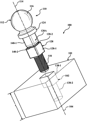
1. A ball joint subassembly comprising:
a component having a thickness, defining a stepped bore extending through the thickness, centered on and extending along a bore axis, and having a reaction surface orthogonal to the bore;
a ball stud extending along stud axis and engaging the component, the ball stud having:
a ball first end;
a threaded second end;
a shank extending along the stud axis between the first and second ends, having a stepped shank shape, and extending through the stepped bore and leaving a gap between the stepped bore and the stepped shank shape
a flange arranged between the ball first end and the shank, having a flange surface arranged orthogonal to the stud axis, and configured to engage and abut the reaction surface; and
a sleeve having a sleeve center axis and positioned on the shank inside the bore; and
a threaded nut engaged with the threaded second end to tighten the ball stud on the component and deform the sleeve in the gap between the stepped bore and the stepped shape shank such that the sleeve fills at least part of the gap.
|