| CPC F15B 11/072 (2013.01) [F15B 13/028 (2013.01); F15B 15/1428 (2013.01); F15B 15/1447 (2013.01); F15B 15/226 (2013.01); F15B 13/0402 (2013.01); F15B 2211/329 (2013.01); F15B 2211/6355 (2013.01)] | 6 Claims |

|
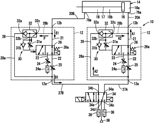
1. A flow rate controller, comprising:
a cylinder flow path communicating with a port of an air cylinder;
a main flow path configured to supply high pressure air and discharge exhaust air to and from the cylinder flow path;
an auxiliary flow path disposed in parallel with the main flow path and including a first throttle valve configured to throttle a flow rate of the air to a flow rate less than that in the main flow path;
a switching valve incorporated in the main flow path and the auxiliary flow path, the switching valve being configured to be switched between a first position in which the cylinder flow path is allowed to communicate with the main flow path, and a second position in which the cylinder flow path is allowed to communicate with the auxiliary flow path; and
a pilot air adjustment part configured to guide a portion of exhaust air in the cylinder flow path to the switching valve as pilot air,
wherein the pilot air adjustment part includes a second throttle valve configured to regulate an inflowing speed at which the pilot air flows into the switching valve, and the switching valve is switched from the first position to the second position due to a rise in a pressure of the pilot air,
further comprising:
a bypass flow path configured to bypass the switching valve and connect the cylinder flow path and the main flow path; and
a shuttle valve including a first inlet, a second inlet, and an outlet, wherein a first portion of the bypass flow path that communicates with the main flow path is connected to the first inlet, a second portion of the bypass flow path that communicates with the cylinder flow path is connected to the outlet, and the pilot air adjustment part is connected to the second inlet,
wherein, when a pressure in the main flow path becomes higher than a pressure in the cylinder flow path, the shuttle valve closes the second inlet to allow the first inlet and the outlet to communicate with each other, and when the pressure in the cylinder flow path becomes higher than the pressure in the main flow path, the shuttle valve closes the first inlet to allow the second inlet and the outlet to communicate with each other.
|