| CPC F02M 41/10 (2013.01) [F02M 59/367 (2013.01); F02M 59/464 (2013.01); F02M 63/0245 (2013.01)] | 20 Claims |

|
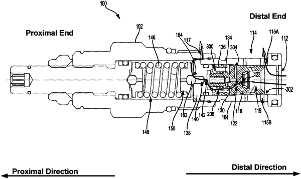
1. A valve comprising:
a piston configured to block fluid flow from a first port of the valve to a second port of the valve when the valve is in a closed position;
a relief mode spring applying a first biasing force on the piston in a distal direction;
a reverse flow spring applying a second biasing force on the piston in a proximal direction, wherein the reverse flow spring is weaker than the relief mode spring; and
a pressure setting spring applying a third biasing force on a check element in the distal direction, causing the check element to be seated when the valve is in the closed position, wherein the valve operates in: (i) a first mode of operation, wherein fluid received at the first port overcomes the third biasing force of the pressure setting spring, thereby unseating the check element and allowing pilot fluid to flow from the first port to the second port, wherein a first net fluid force is applied on the piston that overcomes the first biasing force of the relief mode spring, causing the piston to move in the proximal direction and allow fluid flow from the first port to the second port, and (ii) a second mode of operation, wherein a second net fluid force is applied on the piston that overcomes the second biasing force of the reverse flow spring, causing the piston to move in the distal direction and allow fluid flow from the second port to the first port.
|