| CPC F01D 5/3053 (2013.01) [F01D 5/225 (2013.01); F05D 2220/32 (2013.01); F05D 2240/30 (2013.01)] | 14 Claims |

|
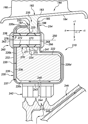
1. A rotor blade assembly for a turbine engine, comprising:
an airfoil blade comprising an inner diameter end and an outer diameter end;
a lower blade carrier coupled to the inner diameter end of the airfoil blade and rigidly coupled to a disk via a pin;
an upper blade carrier coupled to the outer diameter end of the airfoil blade;
an outer drum coupled to the upper blade carrier via a radial joint, wherein the radial joint supports radial motion of the upper blade carrier relative to an axis extending through a center of the rotor blade assembly; and
an outer shroud, wherein the outer shroud is coupled to the outer drum via a centering rabbet and a spline joint, the outer shroud being spaced from the radial joint in a longitudinal direction;
wherein the pin includes a first locking component and a second locking component arranged along a longitudinal axis of the pin, each locking component comprising a first angled surface and a second angled surface that is angled in an opposite direction to the first angled surface, the second angled surface of the first locking component being engaged with the first angled surface of the second locking component in an overlapping configuration.
|