|
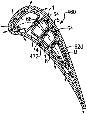
1. An airfoil comprising: an airfoil wall defining a leading end, a trailing end, a pressure side, a suction side, and a mean line from the leading end to the trailing end that is equidistant from the pressure side and the suction side; and first and second ribs each connecting the pressure side and the suction side, the first rib being forward of the second rib, each of the first and second ribs defining: a tube portion circumscribing a rib passage, the tube portion having fore and aft tube walls, a pressure side tube wall parallel to the pressure side of the airfoil wall, and a suction side tube wall parallel to the suction side of the airfoil wall, the pressure side tube wall and the suction side tube wall meeting the each of the fore and aft tube walls at a forward pressure side corner, a forward suction side corner, an aft pressure side corner, and an aft suction side corner such that the tube portion has a quadrilateral shape in cross-section taken in a plane perpendicular to a radial direction of the airfoil wall, and first and second connector arms located at, respectively, the forward suction side corner and the aft pressure side corner, the first and second connector arms solely joining the tube portion to, respectively, the suction side and the pressure side; the first rib, the second rib, and the airfoil wall bounding a continuous cooling channel there between, the continuous cooling channel having, when taken in the plane perpendicular to the radial direction of the airfoil wall, a first leg elongated in a direction transverse to the mean line and bound by the fore tube wall of the second rib and the aft tube wall of the first rib, a second leg initiating at, and aftly extending from, an end of the first leg and bound by the pressure side of the airfoil wall, the pressure side tube wall of the second rib, and the second connector arm, and a third leg initiating at, and forwardly extending from, an opposed end of the first leg and bound by the suction side of the airfoil wall, the suction side tube wall of the first rib, and the first connector arm, the first leg, the second leg, and the third leg together defining a Z-configuration when taken in the plane perpendicular to the radial direction of the airfoil wall.
|
