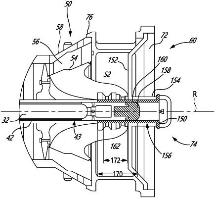
| CPC F01D 25/285 (2013.01) [F01D 25/24 (2013.01); F05D 2220/323 (2013.01); F05D 2230/644 (2013.01); F05D 2230/70 (2013.01); F05D 2230/72 (2013.01); F05D 2230/80 (2013.01)] | 7 Claims |

|
1. A method for installing a mid turbine frame on a gas turbine engine, or removing the mid turbine frame from the gas turbine engine, the mid turbine frame being located between a first turbine rotor and a second turbine rotor in a turbine section of the gas turbine engine during operation of the gas turbine engine, the mid turbine frame rotatably supporting a shaft about a rotation axis and defining a first load path between the shaft and a support structure of the gas turbine engine, the second turbine rotor being uninstalled from the gas turbine engine and the shaft supporting the first turbine rotor, the method comprising:
supporting the shaft on a second load path between the shaft and the support structure of the gas turbine engine, the second load path being different from the first load path;
movably engaging the shaft with a guide and attaching the guide to a holder to permit movement of the holder relative to the shaft along the rotation axis and prevent movement of the holder relative to the shaft transverse to the rotation axis;
with the mid turbine frame attached to the holder and the mid turbine frame released from the support structure of the gas turbine engine, moving the holder and the mid turbine frame together along the rotation axis toward or away from an installed position of the mid turbine frame in the support structure; and
after moving the holder and the mid turbine frame along the rotation axis, either:
attaching the mid turbine frame to the support structure when the holder and the mid turbine frame have been moved toward the installed position of the mid turbine frame; or
releasing the mid turbine frame from the support structure when the holder and the mid turbine frame have been moved away from the installed position of the mid turbine frame.
|