| CPC E21B 43/38 (2013.01) [E21B 33/12 (2013.01); E21B 33/126 (2013.01); E21B 37/06 (2013.01); E21B 41/02 (2013.01); E21B 43/08 (2013.01); E21B 43/084 (2013.01)] | 20 Claims |

|
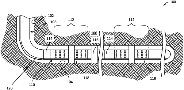
1. A tubular joint installable on a tubular string disposable within a wellbore, the tubular joint comprising:
a perforated section disposed proximate a first end and comprising a first plurality of orifices to allow fluid communication between a bore of the tubular joint and a first area surrounding the tubular joint proximate the perforated section;
a filter section disposed proximate a second end and comprising a filter assembly to filter fluid flowing into the bore via a second plurality of orifices from a second area proximate the filter section;
a packer disposed between the perforated section and the filter section, the packer operable to isolate the first area from the second area when the tubular string is disposed within the well; and
a chemical dispersion system disposed adjacent to the filter section, the chemical dispersion system comprising a first control line and a first dispersion manifold and operable to disperse treatment fluids proximate the filter section to at least reduce a buildup of blockages along the filter assembly.
|