| CPC E21B 43/38 (2013.01) [E21B 43/128 (2013.01)] | 24 Claims |

|
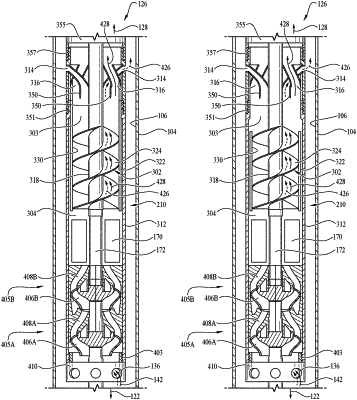
1. A downhole gas separator assembly, comprising:
a drive shaft;
a first fluid mover mechanically coupled to the drive shaft and having a fluid inlet and a fluid outlet;
a fluid reservoir concentrically disposed around the drive shaft and located downstream of the first fluid mover, wherein an inside surface of the fluid reservoir and an outside surface of the drive shaft define a first annulus within a portion of the fluid reservoir that does not enclose a radial support of the drive shaft, wherein the first annulus is fluidically coupled to the fluid outlet of the first fluid mover, wherein when the separator drive shaft is about 0.6875 inches in diameter, the first annulus has a volume of at least 70 cubic inches and less than 100 cubic inches; wherein when the separator drive shaft is about 0.875 inches in diameter, the first annulus has a volume of at least 85 cubic inches and less than 120 cubic inches; wherein when the separator drive shaft is about 1.0 inches in diameter, the first annulus has a volume of at least 180 cubic inches and less than 250 cubic inches; and wherein when the separator drive shaft is about 1.1875 inches in diameter, the first annulus has a volume of at least 220 cubic inches and less than 300 cubic inches;
a second fluid mover having a fluid inlet and a fluid outlet, wherein the second fluid mover is located downstream of the fluid reservoir, and wherein the fluid inlet of the second fluid mover is fluidically coupled to the first annulus;
a separation chamber concentrically disposed around the drive shaft and located downstream of the second fluid mover, wherein an inside surface of the separation chamber and the outside surface of the drive shaft define a second annulus that is fluidically coupled to the fluid outlet of the second fluid mover; and
a crossover defining a gas flow path and liquid flow path separator having a gas phase discharge port open to an exterior of the assembly and a liquid phase discharge port, wherein the gas flow path and liquid flow path separator has a fluid inlet that is fluidically coupled to the second annulus.
|