| CPC E06C 1/12 (2013.01) [E06C 7/06 (2013.01); E06C 7/46 (2013.01)] | 20 Claims |

|
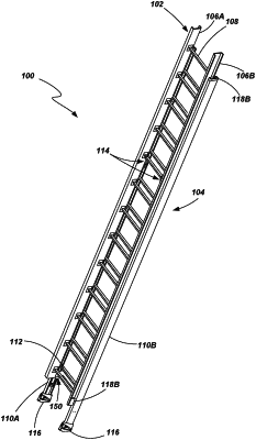
1. A ladder, comprising:
a base section comprising a first pair of spaced apart rails and a first plurality of rungs extending between and coupled to the first pair of spaced apart rails;
a fly section comprising a second pair of spaced apart rails and a second plurality of rungs extending between and coupled to the second pair of spaced apart rails, the fly section being slidably coupled to the base section:
a brace coupled to a lowermost rung of the first plurality of rungs and coupled with the first pair of spaced apart rails, the brace including:
an upper arm,
a first side arm extending down from the upper arm and toward a first rail of the first pair of spaced apart rails,
a second side arm extending down from the upper arm and toward a second rail of the first pair of spaced apart rails,
a first stop member located adjacent a distal end of the first side arm and configured to abut a lower end of a first rail of the second pair of spaced apart rails, and
a second stop member located adjacent a distal end of the second side arm and configured to abut a lower end of a second rail of the second pair of spaced apart rails, wherein the first stop member and the second stop member are configured to elastically deform to absorb energy responsive to a relative motion between the fly section and the base section.
|