| CPC E03C 1/2302 (2013.01) | 20 Claims |
|
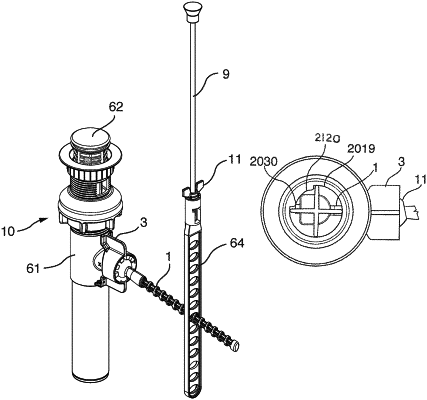
1. A pop-up drain assembly comprising:
a drain body, a drain plug, a horizontal pivot rod, a lock ring, and a lift rod rotatably connected to an outer free end of said horizontal pivot rod;
said drain body being generally cylindrical and comprising a lower unthreaded section, an upper threaded section and a middle unthreaded section with a drain tee connector stem extending outward perpendicularly from said middle section;
said drain tee connector stem including a smooth section terminated by a castellated section containing at least two pawls, each of said at least two pawls including a radially outward protruding step and an inward facing ramped step;
said horizontal pivot rod including an integral spherical ball located a selected length from a first end, said drain plug having an aperture formed therein at a bottom end, said drain plug inserted downward into said drain body, said aperture in said drain plug end aligned with said drain tee connector stem;
said first end of said horizontal pivot rod pushed through said castellated section of said drain tee connector stem, said ball of said horizontal pivot rod pushed through said pawls and snapped into said drain tee connector stem;
said drain tee connector stem having an inner square annular void formed therein capable of receiving a flat ring seal;
a curvature of said inward facing ramped steps matches a curvature of said ball;
said drain tee connector stem having inner vertical guide walls, said horizontal pivot rod having square vertical shoulders cooperatively and slidably engaging said inner vertical guide walls;
said lock ring comprising a hollow cylinder with a pair of wings extending radially outward from outer walls of said lock ring and having downward extending lugs integral to bases of said pair of wings, said downward extending lugs cooperatively pressing against said drain body when said lock ring is tightened, said lock ring having an inner diameter equal to an outer diameter of a circle formed by said outer walls of said at least two pawls, said lock ring having a cylindrical void formed in an outer end thereof for receiving said pawl steps extending radially outward from a free edges of said at least two pawls, said drain body having stop lugs extending radially outward therefrom providing a positive stop to locate said lock ring in a position causing said pawls to apply holding pressure against said ball;
said drain plug comprising a cap, a longitudinal body with longitudinal perpendicular walls and a downward extending drain plug lug having an aperture formed therein;
said first end of said horizontal pivot rod inserting into said drain tee connector stem and into said aperture of said plug lug, and said longitudinal perpendicular walls together forming a cross; and
said drain body having an integral arcuate lug extending radially inward providing a guide cooperatively engaging of said longitudinal perpendicular walls of said cross insuring that said drain plug is positioned properly in said drain body.
|