| CPC E02F 3/382 (2013.01) [B60K 5/12 (2013.01); B62D 51/02 (2013.01); B62D 55/06 (2013.01); B62D 55/10 (2013.01); B62D 55/12 (2013.01); B62D 55/125 (2013.01); B62D 55/18 (2013.01); E02F 3/34 (2013.01); E02F 3/3414 (2013.01); E02F 3/3417 (2013.01); E02F 3/342 (2013.01); E02F 3/422 (2013.01); E02F 9/02 (2013.01); E02F 9/08 (2013.01); E02F 9/0866 (2013.01); E02F 9/0891 (2013.01); E02F 9/2004 (2013.01); E02F 9/2037 (2013.01); E02F 9/22 (2013.01); E02F 9/2221 (2013.01); E02F 9/2267 (2013.01); E02F 9/26 (2013.01); F16D 63/006 (2013.01); E02F 9/2264 (2013.01)] | 30 Claims |

|
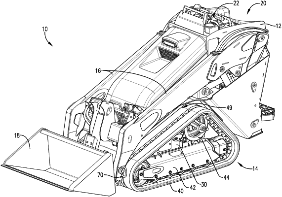
1. A stand-on compact utility loader (CUL) configured for connection to and operation of a variety attachments, the CUL comprising:
a frame;
a platform coupled to the frame near a bottom rear of the frame and configured to support a user while operating the CUL;
a pair of tracks positioned on opposite sides of the frame;
a pair of loader arms coupled to opposite sides of the frame and shiftable relative to the frame between a lowered position and a raised position;
a pair of front and rear links associated with each loader arm and coupling the loader arms to opposite sides of the frame;
a pair of hydraulic cylinders each associated with one of the loader arms and configured to shift the loader arms between the lowered and raised positions;
a pair of pivot pins each associated with one of the loader arms, wherein the pivot pins are configured to connect the attachments to the front of the loader arms, wherein the pivot pins follow a curved travel path from a base position to a maximum height position when the loader arms are shifted from the lowered position to the raised position, wherein the maximum height position is horizontally forward of the base position;
a pair of drive motors fixed to opposite sides of the frame; and
a pair of drive sprockets, each directly attached to one of the drive motors, wherein each of the drive sprockets comprises a plurality of teeth extending radially outward and configured to engage and drive one track from the pair of tracks.
|
|
14. A stand-on compact utility loader (CUL) configured for connection to and operation of a variety attachments, the CUL comprising:
a frame;
a platform coupled to the frame near a bottom rear of the frame and configured to support a user while operating the CUL;
a pair of tracks positioned on opposite sides of the frame;
a pair of loader arms coupled to opposite sides of the frame and shiftable relative to the frame between a lowered position and a raised position;
a pair of front and rear links associated with each loader arm and coupling the loader arms to opposite sides of the frame;
a pair of hydraulic cylinders each associated with one of the loader arms and configured to shift the loader arms between the lowered and raised positions;
a pair of pivot pins each associated with one of the loader arms, wherein the pivot pins are configured to connect the attachments to the front of the loader arms, wherein the pivot pins follow a curved travel path from a base position to a maximum height position when the loader arms are shifted from the lowered position to the raised position, wherein the maximum height position is horizontally forward of the base position;
a drive motor comprising a main motor body fixed to the frame and a rotating drive component extending from the main motor body and rotatable relative to the main motor body; and
a toothed sprocket directly attached to the rotating drive component of the drive motor, wherein the toothed sprocket comprises a plurality of teeth extending radially outward and configured to engage and drive one track from the pair of tracks.
|
|
23. A stand-on compact utility loader (CUL) configured for connection to and operation of a variety attachments, the CUL comprising:
a frame;
a platform coupled to the frame near a bottom rear of the frame and configured to support a user while operating the CUL;
a pair of tracks positioned on opposite sides of the frame;
a pair of loader arms coupled to opposite sides of the frame and shiftable relative to the frame between a lowered position and a raised position;
a pair of front and rear links associated with each loader arm and coupling the loader arms to opposite sides of the frame;
a pair of hydraulic cylinders each associated with one of the loader arms and configured to shift the loader arms between the lowered and raised positions;
a pair of pivot pins each associated with one of the loader arms, wherein the pivot pins are configured to connect the attachments to the front of the loader arms, wherein the pivot pins follow a curved travel path from a base position to a maximum height position when the loader arms are shifted from the lowered position to the raised position, wherein the maximum height position is horizontally forward of the base position;
a drive motor fixed to the frame; and
a drive sprocket attached to the drive motor and configured to engage and drive one track from the pair of tracks, wherein the drive sprocket comprises (i) a circular base with a plurality of teeth extending radially outward therefrom and configured to be engaged with the one track from the pair of tracks, and (ii) a hub positioned radially inward from the base and configured to be coupled with the drive motor, wherein the hub is positioned laterally outward with respect to the base.
|