| CPC B65D 33/24 (2013.01) [B65D 33/255 (2013.01); Y10T 24/45168 (2015.01)] | 7 Claims |

|
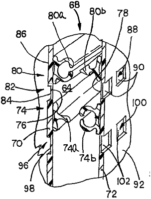
1. A reclosable pouch in combination with an elongate closure mechanism, the reclosable pouch comprising:
(A) first and second sidewalls each having a first surface and a second surface, the first and second sidewalls each extending from a bottom edge to a top edge, and the first and second sidewalls being connected together in order to define an interior space of the pouch between the first and second sidewalls, and a mouth defining an opening into the interior space; and
(B) an elongate closure mechanism disposed along the first and second sidewalls for resealably closing the mouth, the elongate closure mechanism extending longitudinally from one end of the mouth to an opposite end of the mouth, the elongate closure mechanism comprising:
(a) a first interlocking member extending from the first surface of the first sidewall;
(b) a second interlocking member extending from the first surface of the second sidewall, the second interlocking member being configured to occlude and to deocclude with the first interlocking member, in order to resealably close the mouth;
(c) a third interlocking member extending from the first surface of the first sidewall, the third interlocking member being (i) parallel to the first interlocking member extending from the first surface of the first sidewall and (ii) disposed in an area below the first interlocking member, wherein the area that is below the first interlocking member extending from the first surface of the first sidewall comprises a space between the first interlocking member and the third interlocking member extending from the first surface of the first sidewall;
(d) a fourth interlocking member extending from the first surface of the second sidewall, the fourth interlocking member being (i) parallel to the second interlocking member extending from the first surface of the second sidewall and (ii) disposed in an area below the second interlocking member, the third interlocking member extending from the first surface of the first sidewall being configured to occlude and to deocclude with the fourth interlocking member extending from the first surface of the second sidewall;
(e) a plurality of partial indentations being disposed along one of the first surface and the second surface of the first sidewall, the plurality of partial indentations (i) partially extending into the one of the first surface and the second surface of the first sidewall, (ii) consisting of only a single, linear row of longitudinally spaced apart partial indentations that only extends longitudinally between opposite ends of the elongate closure mechanism in at least one of (1) an area that is above the first interlocking member extending from the first surface of the first sidewall and below the top edge of the first sidewall, without extending to the top edge of the first sidewall, and (2) the area that is below the first interlocking member extending from the first surface of the first sidewall that comprises the space between the first interlocking member and the third interlocking member extending from the first surface of the first sidewall, with the single, linear row of partial indentations being disposed only in the at least one of (1) the area that is above the first interlocking member extending from the first surface of the first sidewall and below the top edge of the first sidewall, and (2) the area that is below the first interlocking member extending from the first surface of the first sidewall that comprises the space between the first interlocking member and the third interlocking member extending from the first surface of the first sidewall, to provide a tactile guide path to facilitate a user during occluding of the first and second interlocking members, and (iii) being visible between the opposite ends of the elongate closure mechanism, wherein the plurality of partial indentations remains visible during occluding and deoccluding of the first interlocking member with the second interlocking member; and
(f) a plurality of partial indentations disposed along one of the first surface and the second surface of the second sidewall in a space between the second interlocking member and the fourth interlocking member extending from the first surface of the second sidewall.
|