| CPC B64D 33/08 (2013.01) [B64C 27/08 (2013.01); B64C 27/20 (2013.01); B64C 39/024 (2013.01); B64U 10/13 (2023.01); B64U 30/20 (2023.01); B64U 50/14 (2023.01)] | 18 Claims |

|
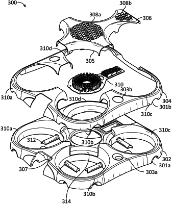
1. An airframe assembly for an unmanned aerial vehicle (UAV), the airframe assembly comprising:
a top airframe assembly comprising a top foam airframe core at least partially enclosed within a top airframe shell; and
a bottom airframe assembly comprising a bottom foam airframe core at least partially enclosed within a bottom airframe shell and coupled to the top airframe assembly, wherein:
the top and bottom foam airframe cores form one or more rotor ducts;
each rotor duct comprises an inlet and a diffusor outlet shaped to increase a thrust efficiency of a propulsion system for the UAV;
the top airframe assembly comprises a metal heat sink assembly disposed at least partially between the top foam airframe core and the top airframe shell and configured to cool at least power electronics of the UAV; and
the top airframe shell comprises a plurality of cooling air inlet orifices configured to allow ambient air to reach a dissipation surface of the metal heat sink assembly.
|