| CPC B64C 27/48 (2013.01) [B64C 27/10 (2013.01); B64C 27/35 (2013.01); B64C 27/26 (2013.01); B64C 2027/8236 (2013.01); B64C 2027/8272 (2013.01); B64C 2027/8281 (2013.01)] | 20 Claims |

|
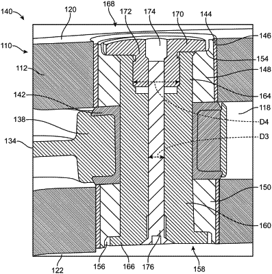
1. A rotor blade retention assembly comprising:
a central hub,
a rotor blade comprising an upper outer surface, a lower outer surface, a blade hole, and a proximal end coupled to the central hub;
a strap member extending along a portion of the rotor blade such that a distal end receiving portion of the strap member extends into the blade hole; and
a retainer assembly disposed within the blade hole and coupled to the strap member, the retainer assembly comprising:
an upper bushing slidably disposed within the blade hole and extending between the strap member and the upper outer surface of the rotor blade, the upper bushing comprising an upper counterbored portion,
a lower bushing slidably disposed within the blade hole and extending between the strap member and the lower outer surface of the rotor blade,
an outboard blade pin disposed within the distal end receiving portion of the strap member, the outboard blade pin comprising a blade pin inner cavity,
a first fastener disposed within the upper counterbored portion, and
a second fastener extending through the blade pin inner cavity and coupled to the first fastener such that the first fastener, the outboard blade pin, and the second fastener cooperatively clamp the lower bushing and the upper bushing to the strap member.
|