| CPC B61G 7/10 (2013.01) [B61G 1/22 (2013.01); B61G 1/28 (2013.01); B61G 1/32 (2013.01); B61G 7/06 (2013.01); B61G 7/08 (2013.01); B61G 7/12 (2013.01); B61G 5/02 (2013.01); B61G 5/04 (2013.01); B61G 11/04 (2013.01)] | 6 Claims |

|
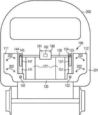
1. A coupling support to be fixed to a vehicle body of a rail vehicle for supporting a central buffer coupling of the rail vehicle, the coupling support comprising:
first and second retaining plates to be fixed to the vehicle body of the rail vehicle;
a base plate disposed between said first and second retaining plates;
a transverse bar disposed between said retaining plates, said transverse bar being resiliently coupled to said base plate and disposed above said base plate;
first and second pivot levers disposed on said base plate, said first pivot lever having a first pivot location disposed under said transverse bar, said second pivot lever having a second pivot location disposed under said transverse bar, said first and second pivot locations being connected to said base plate, said first pivot lever having a first upper portion and said second pivot lever having a second upper portion;
first and second articulated connections each forming a vertical stop of said transverse bar, said first articulated connection connecting said first upper portion to said transverse bar and said second articulated connection connecting said second upper portion to said transverse bar, said articulated connections limiting a movement of said transverse bar away from said base plate and said articulated connections permitting a movement of said transverse bar toward said base plate;
said first articulated connection having a first bolt disposed on said transverse bar, said first bolt being guided in a first elongate hole formed in said first pivot lever; and
said first pivot lever having an adjustable vertical stop for changing an available length of said first elongate hole.
|