| CPC B29C 45/0046 (2013.01) [A61M 5/178 (2013.01); A61M 5/3129 (2013.01); A61M 5/31515 (2013.01); B29C 45/0025 (2013.01); B29C 45/062 (2013.01); B29C 45/1618 (2013.01); B29C 45/164 (2013.01); B29C 45/261 (2013.01); A61M 2207/00 (2013.01); A61M 2207/10 (2013.01); B29C 2045/0027 (2013.01); B29L 2031/7544 (2013.01)] | 8 Claims |

|
1. A syringe comprising:
a barrel having a proximal end, a distal end, and a sidewall extending substantially circumferentially between the proximal end and the distal end along a longitudinal axis;
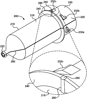
a drip flange extending radially outward from the barrel, the drip flange having a pair of protrusions protruding axially relative to the drip flange and extending radially from an edge of the drip flange to the sidewall along at least one of a top surface and a bottom surface of the drip flange; and
a pair of gate marks each formed on one of the pair of protrusions on the drip flange,
wherein the barrel is formed from an injection molding process comprising:
aligning a mold die defining an internal shape of the barrel in a molding cavity defining an external shape of the barrel, the molding cavity defined by a first mold section and a second mold section, each mold section comprising a gate adapted to control flow of a molding material into the molding cavity, the gate of the first mold section located diametrically opposite the gate of the second mold section within the molding cavity;
supplying a first melt stream of the molding material to the gate of the first mold section, and supplying a second melt stream of the molding material to the gate of the second mold section; and
opening the gate of the first mold section and the gate of the second mold section to permit the molding material from the first melt stream and the second melt stream to fill the molding cavity surrounding the mold die, wherein the molding material takes a shape of the molding cavity, and
wherein a first of the pair of gate marks is formed on the drip flange at a location of the gate of the first mold section and a second of the pair of gate marks is formed on the drip flange at the location of the gate of the second mold section.
|