| CPC B25B 23/005 (2013.01) [B25B 23/10 (2013.01)] | 16 Claims |

|
1. A method of using a guide, the method comprising:
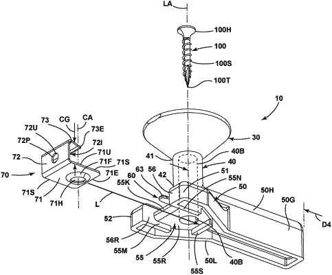
providing a guide including an upward opening funnel having an upper end and a lower end, with an elongated barrel extending downward from the lower end to a guide base, the guide base including a handle extending laterally from the guide base and including a grasping surface configured so a user can grasp and manipulate the guide, the guide base defining a guide recess disposed below the elongated barrel; and
installing a clip on the guide so that a clip base enters the guide recess, the clip including a clip wall extending upward from the clip base, the clip wall joined with a clip arm that extends over the clip base, the clip base defining a fastener hole, the fastener hole aligned with the elongated barrel,
wherein the clip arm, clip base and clip wall form a C shape,
wherein the clip wall extends vertically between the clip base and the clip arm,
wherein the clip base includes a clip base end and extends laterally from the clip wall,
wherein the clip arm includes a clip arm end and extends laterally from the clip wall,
wherein the clip base end extends laterally farther from the clip wall than the clip arm end on a same side of the clip wall as the clip arm end,
wherein the guide base includes a retainer extending outward from the guide base,
wherein the retainer engages the clip and secures the clip to the guide,
wherein the retainer includes a pin extending from the guide base,
wherein the clip defines a pin hole in the clip wall,
wherein the pin extends completely through the pin hole, from one side of the clip wall to an opposing side, thereby extending through the clip wall and projecting therefrom on the opposing side
whereby the handle is graspable by a user to impair rotation of the clip as the clip is installed relative to a workpiece.
|
|
9. A method of using a guide, the method comprising:
providing a guide including an upward opening funnel with an elongated barrel defining a fastener bore extending downward from the upward opening funnel, and a guide base including a handle extending from the guide base and including a grasping surface configured so a user can grasp and manipulate the guide, the guide base defining a guide recess disposed below the elongated barrel, and a retention element;
installing a clip on the guide so that a clip base enters the guide recess, passing a forward wall, the clip including a clip wall extending upward from the clip base, the clip wall joined with a clip arm that extends over the clip base, the clip base defining a fastener hole, the fastener hole aligned with the fastener bore;
pushing the guide base against a structure vertical wall so that the forward wall engages the structure wall to establish a distance between the structure vertical wall and a clip axis;
providing a pin hole in the clip wall; and
projecting a pin completely through the pin hole, so that the pin projects through the clip wall from one side of the clip wall, to and beyond an opposing side of the clip wall, to exert a force on the clip and retain the clip on the guide with the clip base disposed in the guide recess,
whereby the handle is graspable by a user to impair rotation of the clip as the clip is installed relative to a workpiece.
|
|
15. A clip fastener guide comprising:
an upward opening funnel having an upper end and a lower end;
an elongated barrel joined with the lower end;
a guide base joined with the elongated barrel, the guide base including a handle extending from the guide base with a grasping surface configured so a user can grasp and manipulate the guide, the guide base defining a guide recess disposed below the elongated barrel;
clip joined with the guide so that a clip base is disposed in the guide recess, the clip including a clip wall extending upward from the clip base, the clip wall joined with a clip arm that extends over the clip base, the clip base defining a fastener hole, the fastener hole aligned with the elongated barrel when the clip base is disposed in the guide recess;
a pin projecting from the guide base; and
a pin hole defined by the clip,
wherein the clip arm, clip base and clip wall form a C shape,
wherein the clip wall extends vertically between the clip base and the clip arm,
wherein the clip base includes a clip base end and extends laterally from the clip wall,
wherein the clip arm includes a clip arm end and extends laterally from the clip wall,
wherein the clip base end extends laterally farther from the clip wall than the clip arm end on a same side of the clip wall as the clip arm end,
wherein the pin extends completely through the pin hole defined by the clip, so that the pin projects through the clip wall from one side of the clip wall, to and beyond an opposing side of the clip wall,
wherein the pin exerts a force against the clip to urge the clip base into the guide recess,
whereby the handle is graspable by a user to impair rotation of the clip as the clip is installed relative to a workpiece.
|