| CPC B21D 28/34 (2013.01) [B21D 39/048 (2013.01); B25B 27/10 (2013.01); B30B 15/026 (2013.01)] | 12 Claims |

|
1. A die retainer for use in a tool with a die, the die retainer comprising:
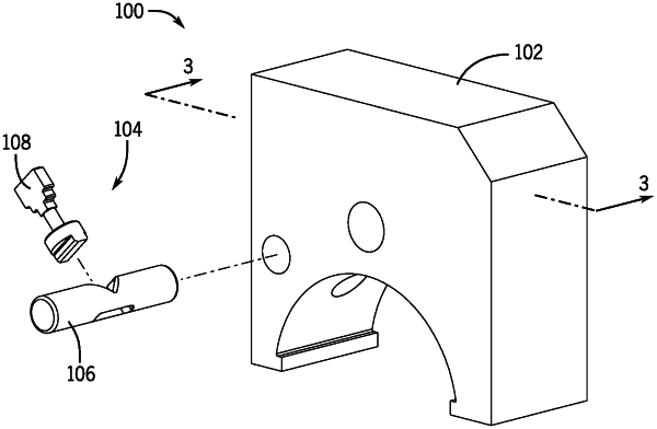
a ram head including a die engagement surface that defines a die cavity, a pair of lateral surfaces on opposing sides of the die cavity, a release button hole, and a die pin cavity that intersects the release button hole;
a release button that extends through the release button hole, the release button including a pair of opposing ends, each one of which extends past one of the pair of lateral surfaces, the release button including a slot, the slot extending between a first slot end and a second slot end, the second slot end defining a notch, the notch having at least one sloped surface; and
a die pin that extends through the die pin cavity, the die pin including a button engaging portion configured to move along the at least one sloped surface of the release button and a die engaging portion that extends past the die engagement surface of the ram head into the die cavity to retain the die.
|