| CPC B01D 1/14 (2013.01) [B01D 1/0082 (2013.01); B01D 1/20 (2013.01); B01D 1/305 (2013.01); B01D 19/04 (2013.01); B05B 1/26 (2013.01); C02F 1/008 (2013.01); C02F 1/042 (2013.01); C02F 1/048 (2013.01); C02F 1/12 (2013.01); C02F 1/50 (2013.01); C02F 1/66 (2013.01); C02F 5/08 (2013.01); C02F 2201/005 (2013.01); C02F 2209/006 (2013.01); C02F 2209/008 (2013.01); C02F 2209/02 (2013.01); C02F 2209/03 (2013.01); C02F 2209/05 (2013.01); C02F 2209/06 (2013.01); C02F 2209/38 (2013.01); C02F 2209/40 (2013.01); C02F 2303/04 (2013.01); C02F 2303/12 (2013.01); C02F 2303/22 (2013.01); C02F 2303/26 (2013.01); E21B 41/005 (2013.01); E21B 43/34 (2013.01); Y02E 10/10 (2013.01)] | 54 Claims |
|
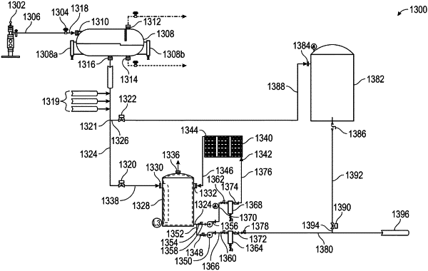
1. A produced water evaporation system for spray evaporating water comprising:
a. a geothermal heat retainment system having:
i. a first feed inlet; and
ii. a first discharge outlet; and
iii. a first feed tank having a first inlet, a second inlet and an outlet, wherein the first feed inlet is fluidly connected to the first inlet to the first feed tank;
iv. a first feed pump having an inlet and an outlet, wherein the outlet to the first feed tank is fluidly connected to the inlet to the first feed pump and wherein the outlet to the first feed pump is fluidly connected to the first discharge outlet;
v. a second recirculation pump having an inlet and an outlet, wherein the outlet to the first feed tank is fluidly connected to the inlet to the second recirculation pump;
b. an evaporation system having:
i. a second feed inlet, wherein the first discharge outlet is fluidly connected to the second feed inlet;
ii. a pump, wherein an outlet of the second feed inlet is fluidly connected to an inlet of the pump and wherein an outlet of the pump is fluidly connected to an inlet of a manifold;
iii. a drip manifold comprising a drip orifice, wherein an outlet of the manifold is fluidly connected to an inlet of the drip manifold;
iv. a container, wherein a first portion of a ceiling of the container is constituted by a demister element such that the first portion of the ceiling is entirely configured as an outlet for evaporated water and wherein a second portion of the ceiling is adjacent to an upper edge of a wall of the container;
v. a packing system and/or a tray system disposed within the container, wherein the drip orifice discharges produced water and/or water droplets onto the packing system and/or tray system;
vi. a second discharge outlet, wherein a bottom of the container is fluidly connected to the second discharge outlet; and
vii. an air system comprising an air blower and an optional air preheater;
wherein the air system is disposed through the wall of the container and wherein the air system discharges air flow counter to the produced water and/or water droplets from the drip orifice, wherein the air blower produces an air flow rate from about 2,500 CFM to about 20,000 CFM.
|