| CPC B01D 1/14 (2013.01) [B01D 1/0082 (2013.01); B01D 1/20 (2013.01); B01D 1/305 (2013.01); B01D 19/04 (2013.01); B05B 1/26 (2013.01); C02F 1/008 (2013.01); C02F 1/042 (2013.01); C02F 1/048 (2013.01); C02F 1/12 (2013.01); C02F 1/50 (2013.01); C02F 1/66 (2013.01); C02F 5/08 (2013.01); C02F 2201/005 (2013.01); C02F 2209/006 (2013.01); C02F 2209/008 (2013.01); C02F 2209/02 (2013.01); C02F 2209/03 (2013.01); C02F 2209/05 (2013.01); C02F 2209/06 (2013.01); C02F 2209/38 (2013.01); C02F 2209/40 (2013.01); C02F 2303/04 (2013.01); C02F 2303/12 (2013.01); C02F 2303/22 (2013.01); C02F 2303/26 (2013.01)] | 72 Claims |

|
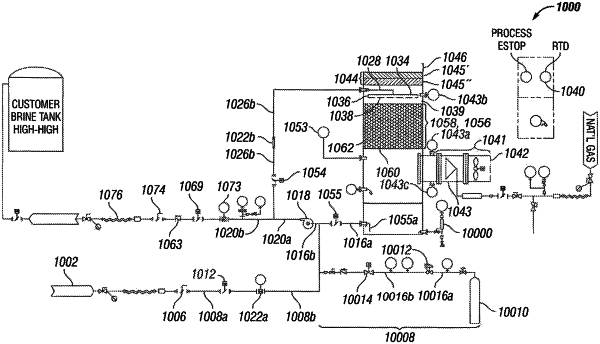
1. A wastewater evaporation system for spray evaporating water comprising:
a. a wastewater feed inlet;
b. a pump, wherein an outlet of the wastewater inlet is fluidly connected to an inlet of the pump and wherein an outlet of the pump is fluidly connected to both:
an inlet of a manifold via a feed valve downstream of the pump, and
a discharge outlet via a discharge valve downstream of the pump;
c. a drip manifold comprising a drip orifice, wherein an outlet of the manifold is fluidly connected to an inlet of the drip manifold;
d. a container, wherein a first portion of a ceiling of the container is constituted by a demister element such that the first portion of the ceiling is entirely configured as an outlet for evaporated water and wherein a second portion of the ceiling is adjacent to an upper edge of a wall of the container;
e. a packing system and/or a tray system disposed within the container, wherein the drip orifice discharges wastewater and/or water droplets onto the packing system and/or tray system;
f. the discharge outlet, wherein a bottom of the container is fluidly connected to the discharge outlet; and
g. an air system comprising an air blower and an air preheater;
wherein the air system is disposed through the wall of the container and wherein the air system discharges air flow counter to the wastewater and/or water droplets from the drip orifice, wherein the air blower produces an air flow rate from about 4,500 CFM to about 25,000 CFM; and
wherein the outlet of the pump is selectively fluidly connected to cause:
a first fluid flow from the outlet of the pump to the manifold via the feed valve,
a second fluid flow from the outlet of the pump to the discharge outlet via the discharge valve, and
the first fluid flow and the second fluid flow simultaneously.
|