| CPC A63B 53/08 (2013.01) [A63B 53/0433 (2020.08); A63B 53/0437 (2020.08); A63B 53/0466 (2013.01); A63B 2053/0491 (2013.01); A63B 2209/02 (2013.01)] | 18 Claims |

|
1. A fairway-type golf club head comprising:
a club head comprising:
a main body comprising:
a front portion comprising a front opening,
a rear portion,
a toe portion, and
a heel portion;
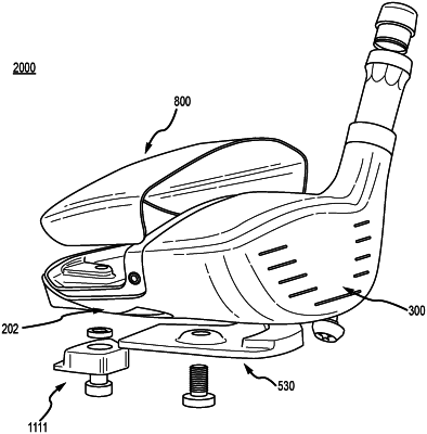
a sole defining an insert recess;
a crown return;
wherein the rear portion, the toe portion, the heel portion, the sole, and the crown return define a crown aperture;
a face cup received within the front opening;
wherein the face cup comprises a strike face having a geometric center;
a sole insert received within the insert recess;
wherein the insert recess is recessed into the sole towards the crown return via an insert recess floor;
wherein the sole insert is formed from a material having a sole insert density greater than 15 g/cm3;
wherein the sole insert comprises a mass between 70 grams to 90 grams;
wherein the sole insert defines a surface area visible from an exterior of the club head;
wherein the surface area is between 3.00 in2 to 3.50 in2;
a crown insert received within the crown aperture;
wherein the crown insert, and the crown return define a crown;
a club head volume of less than 200 cm3;
a loft angle between 14 degrees and 35 degrees; and
a club head center of gravity (CG);
wherein the club head defines:
a ground plane tangent to the sole of the club head;
a loft plane tangent to the strike face at the geometric center;
a coordinate system originating at the geometric center of the strike face comprising an X axis, a Y axis, and a Z axis;
wherein the Z axis extends in a front-to-rear direction parallel to the ground plane;
wherein the Y axis extends in a crown-to-sole direction perpendicular to the Z axis; and
wherein the X axis extends in a heel-to-toe direction perpendicular to the Y axis and the Z axis;
a YZ plane through the geometric center and along the Y axis and Z axis;
a force line impact point (FLIP) located on the strike face at a vertical distance from the ground plane ranging from 0.55 inch to 0.75 inch, and on the YZ plane; and
a force line impact point (FLIP) axis extending rearward from the FLIP and perpendicular to the strike face at the FLIP;
wherein:
the club head CG is located at a CGX1, a CGY1, and a CGZ1, wherein:
the CGX1 is measured parallel to the X axis from the geometric center, and the CGX1 is in a range of 0.010 inch to 0.020 inch;
the CGY1 is measured perpendicularly from the Z axis, and the CGY1 is in a range of 0.20 inch to 0.30 inch;
the CGZ1 is measured parallel to the Z axis and rearward from the geometric center, and the CGZ1 is in a range of 1.00 inch to 1.25 inch;
the CGX1, the CGY1, and the CGZ1 define an imaginary rectangular box;
the club head CG is located within the imaginary rectangular box, and;
wherein:
the club head CG is further located at a CGF1 measured perpendicularly from the club head CG to the FLIP axis; and
the CGF1 is in a range of 0.000 inch to 0.040 inch.
|