|
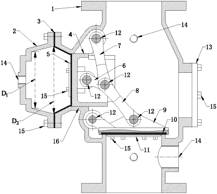
1. A main valve for drawing a straightway deluge valve, comprising a valve body, a valve cover, a diaphragm, a drawing piston, a diaphragm pressure plate, a drawing link, a valve body link, a valve plate link, a rotatable lip and a mounting hole cover; the valve body has a top and a bottom communicated to each other, to form a flow passage; a lower portion of the valve body is of stepped structure and has an inner sealing end surface; a piston guide is provided at a side part of the valve body; the drawing piston is slidably provided in the piston guide along a left-right direction, the valve cover is connected to the piston guide through flanges, the diaphragm pressure plate is fixedly connected to the drawing piston; a middle portion of the diaphragm is clamped between the diaphragm pressure plate and the drawing piston; an edge of the diaphragm is clamped between the valve cover and the piston guide; a side wall of the valve body and the valve cover each have a threaded through hole provided therein; a mounting hole is also provided at another side portion of the valve body; the mounting hole cover is sealingly fixed at the mounting hole; a first end of the drawing link, a first end of the valve body link and a first end of the valve plate link are rotatably connected with each other; a second end of the drawing link is rotatably connected to one side of the drawing piston away from the diaphragm; a second end of the valve body link is rotatably connected to an upper inner wall of the valve body; a second end of the valve plate link is rotatably connected to an upper portion of the rotatable lip; one end of the rotatable lip is rotatably connected to a lower inner wall of the valve body; when the drawing piston slides along the piston guide, the rotatable lip is able to in contact with or separate from the inner sealing end surface.
|
