| CPC A61F 2/4465 (2013.01) [A61F 2/44 (2013.01); A61F 2/442 (2013.01); A61F 2/4425 (2013.01); A61F 2/4455 (2013.01); A61F 2/4611 (2013.01); A61F 2/4684 (2013.01); A61B 17/8095 (2013.01); A61F 2002/3008 (2013.01); A61F 2002/30228 (2013.01); A61F 2002/30235 (2013.01); A61F 2002/30383 (2013.01); A61F 2002/30405 (2013.01); A61F 2002/30433 (2013.01); A61F 2002/30467 (2013.01); A61F 2002/30495 (2013.01); A61F 2002/30515 (2013.01); A61F 2002/30517 (2013.01); A61F 2002/30523 (2013.01); A61F 2002/30538 (2013.01); A61F 2002/30556 (2013.01); A61F 2002/30565 (2013.01); A61F 2002/4415 (2013.01); A61F 2002/443 (2013.01); A61F 2220/0041 (2013.01)] | 17 Claims |

|
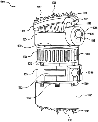
1. An expandable vertebral implant assembly comprising:
an inner member;
an outer member;
a gear coupled to the inner and outer members and adapted to move the inner member relative to the outer member upon rotation of the gear; and
a polyaxial endplate assembly attached to at least one of the inner member and the outer member, and including:
an endplate including a circumferential inner surface and a curved exterior surface and a plurality of gear teeth circumferentially arranged on the curved exterior surface;
a mating body including a curved inner surface and mating teeth arranged circumferentially on the curved inner surface, the mating teeth enmesh with the gear teeth of the endplate; and
a clamp disposed to press the endplate relative to the mating body to fix the endplate to the mating body at a desired angle, the clamp having a convex surface configured to contact the circumferential inner surface of the endplate; and
a clamping screw coupled to the mating body and the clamp.
|