| CPC A61B 17/7037 (2013.01) [A61B 17/7032 (2013.01)] | 20 Claims |
|
1. A method of assembling a pivotal bone anchor assembly with tooling, the method comprising:
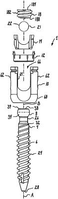
applying the tooling to a receiver assembly comprising a receiver, a retainer and a pressure insert, the pressure insert comprising an outer abutment surface including an upper surface part and a lower surface part, the pressure insert being in a first position in a central bore of the receiver, the pressure insert including a central through-bore and an upwardly open rod seat, the receiver comprising a base defining a lower portion of the central bore centered about a vertical centerline axis and communicating with a bottom surface of the receiver through a bottom opening, and a pair of upright arms extending upwardly from the base to define an open channel extending between a front side and a back side of the receiver and forming an upper portion of the central bore, the central bore extending upwardly through the open channel to tops of the upright arms and flanked on both sides by opposed substantially-planar surfaces extending between the central bore and the front side and the back side of the receiver and extending parallel with respect to the vertical centerline axis, the central bore including a narrower engagement portion adjacent the bottom opening, a wider expansion portion above the narrower engagement portion, and an inwardly-projecting arcuate interference wedging surface above the wider expansion portion extending horizontally between the opposed substantially-planar surfaces flanking the central bore, the inwardly-projecting arcuate interference wedging surface including an upper surface portion and a lower surface portion, the upper surface portion being engageable with the lower surface part of the pressure insert in the first position to inhibit downward movement of the pressure insert in the open channel without an exterior force being applied on the pressure insert by the tooling, the retainer being positioned within the wider expansion portion of the central bore below the pressure insert with an upper part of the retainer being received within a lower recess of the pressure insert, the retainer configured to widen within the expansion portion;
uploading a capture portion of a bone anchor through the bottom opening of the receiver and into the retainer to cause the retainer to first widen within the expansion portion of the central bore to receive the capture portion, and then to close around and contain the capture portion within the central bore while providing for pivotal motion of the bone anchor relative to the receiver;
after the capture portion of the bone anchor is uploaded through the bottom opening and contained within the retainer, downwardly displacing the pressure insert within the central bore with the tooling until the lower surface part of the outer abutment surface of the pressure insert is forced at least partially past the upper surface portion of the inwardly-projecting arcuate interference wedging surface of the central bore into a second position so as to inhibit the pressure insert from moving back up within the receiver, with the retainer also being downwardly displaced until an outer surface of the retainer engages with an interior surface of the narrower engagement portion to impede repeat widening of the retainer;
after the downward displacement of the retainer and the pressure insert, installing a longitudinal connecting member into the receiver and into engagement with the upwardly-open rod seat of the pressure insert; and
securing the longitudinal connecting member within the receiver with a closure.
|