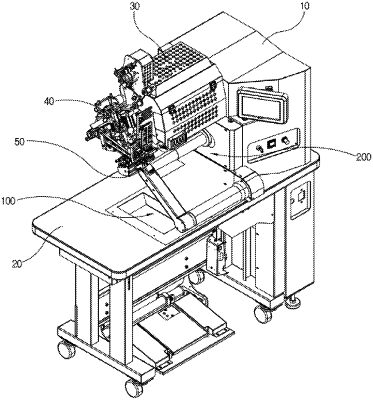
| CPC A41H 43/04 (2013.01) [B29C 65/10 (2013.01); B29C 66/729 (2013.01); B29C 66/82 (2013.01); B29L 2031/48 (2013.01)] | 5 Claims |

|
1. A lower roller structure of a hot air welder which comprises
a main body having a worktable plate installed on one side of a middle portion thereof,
a support arm unit which has a vertically movable upper roller at an upper portion of the main body, and extends to an upper side of the worktable plate,
wherein the lower roller structure is configured to press a fabric with the upper roller to perform hot welding, the lower roller structure comprising:
a first lower roller unit including a first lower roller which is provided at one side of the main body on the upper side of the worktable plate, and is pivoted vertically corresponding to the upper roller; and
a second lower roller unit including a second lower roller which is provided at a side surface of the main body on an upper side of the first lower roller unit and is slidably movable in front and rear corresponding to the upper roller;
wherein the first lower roller unit and the second lower roller unit are replaceable with each other so that one of the first lower roller and the second lower roller performs a welding operation on a flat fabric or a cylindrical fabric in association with the upper roller,
wherein the second lower roller unit comprises:
a guide rail provided obliquely upward from the front to the rear on one side of the main body;
a moving plate slidably coupled to the guide rail and having a guide roller;
a guide tube whose rear end penetrates the moving plate, which extends toward the upper roller, and has the second lower roller installed at one end thereof;
a second drive cylinder installed on the main body and connected to the moving plate by a piston rod to slide the moving plate in front and rear; and
a moving plate stopper screwed to a support block on a front side of the main body to limit a forward moving force of the moving plate,
wherein the second lower roller is positioned under or spaced apart from the upper roller by the sliding of the moving plate.
|