| CPC A24F 40/50 (2020.01) [A24F 40/40 (2020.01); A24F 40/53 (2020.01); A24F 40/57 (2020.01); A24F 40/10 (2020.01); A24F 40/51 (2020.01)] | 21 Claims |

|
1. An electronic vapor provision system comprising:
a vaporizer for vaporizing aerosol precursor material for inhalation by a user of the electronic vapor provision system;
a power supply for supplying power to the vaporizer;
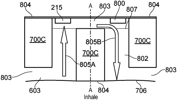
a wall defining an air flow path along which air travels through the electronic vapor provision system when a user inhales or exhales on the electronic vapor provision system;
a heatable temperature sensor mounted in the air flow path adjacent a portion of the wall of the air flow path; and
a controller configured to cause power to be supplied to the heatable temperature sensor to heat the heatable temperature sensor to a temperature above ambient temperature and to cause power to be supplied to the vaporizer to vaporize the aerosol precursor material in response to detecting a change in temperature of the heatable temperature sensor;
wherein the air flow path is arranged such that, during inhalation by the user, air travelling along the air flow path is directed at the heatable temperature sensor in a direction that is towards the portion of the wal adjacent to which the heatable temperature sensor is mounted so as to disrupt the airflow around the heatable temperature sensor.
|
|
21. A method of operating an electronic vapor provision system comprising a vaporizer for vaporizing aerosol precursor material for inhalation by a user of the electronic vapor provision system, a power supply for supplying power to the vaporizer, a wall defining an air flow path along which air travels through the electronic vapor provision system when a user inhales or exhales on the electronic vapor provision system, and a heatable temperature sensor mounted in the air flow path adjacent a portion of the wall of the air flow path, the method comprising:
causing power to be supplied to the heatable temperature sensor to heat the heatable temperature sensor to a temperature above ambient temperature; and
causing power to be supplied to the vaporizer to vaporize the aerosol precursor material in response to detecting a change in temperature of the heatable temperature sensor;
wherein the air flow path is arranged such that, during inhalation by the user, air travelling along the air flow path is directed at the heatable temperature sensor in a direction that is towards the portion of the wall adjacent to which the heatable temperature sensor is mounted so as to disrupt the airflow around the heatable temperature sensor.
|