| CPC H03K 17/08122 (2013.01) [G01R 19/16538 (2013.01); G05F 3/18 (2013.01); H02H 3/18 (2013.01); H03K 17/687 (2013.01)] | 18 Claims |

|
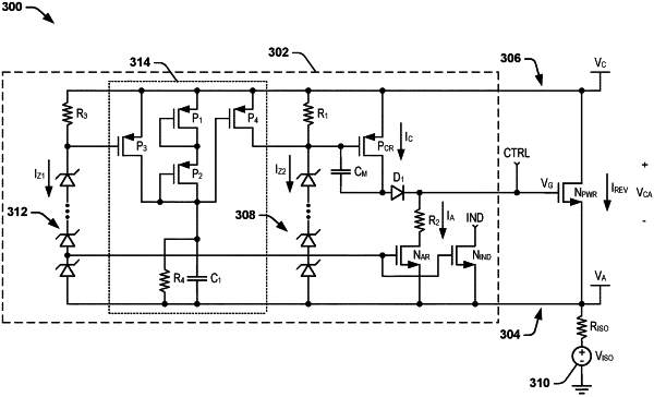
1. A reverse current controller, comprising:
first and second monitoring terminals adapted to be coupled to respective first and second terminals of a power transistor are configured with a power switch as an ideal diode between the first monitoring terminal and the second monitoring terminal;
a control output adapted to be coupled to a control input of the power transistor;
an anode regulation transistor coupled between an input of the power transistor and the first monitoring terminal, the anode regulation transistor being activated in response to a reverse voltage being approximately equal to a threshold amplitude;
a cathode regulation transistor coupled between the input of the power transistor and the second monitoring terminal, wherein the cathode regulation transistor is activated in response to the reverse voltage being approximately equal to the threshold amplitude; and
a Zener diode stack coupled to an input of the anode regulation transistor and an input of the cathode regulation transistor, wherein the Zener diode stack is configured to set the threshold amplitude, and to activate the anode regulation transistor and the cathode regulation transistor in response to the reverse voltage being approximately equal to the threshold amplitude;
wherein the reverse current controller is configured to provide a control signal at the control output to activate the power transistor to conduct a reverse current from the second monitoring terminal to the first monitoring terminal responsive to a reverse voltage associated with a voltage at the second monitoring terminal exceeding a voltage at the first monitoring terminal by the threshold amplitude.
|