| CPC H02K 1/17 (2013.01) [H02K 1/20 (2013.01); H02K 9/19 (2013.01); H02K 21/24 (2013.01)] | 8 Claims |

|
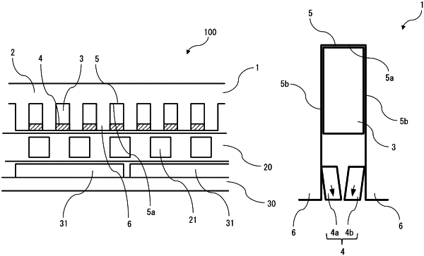
1. A stator comprising:
a stator core including a plurality of stator teeth in a circumferential direction with respect to a center of rotation of a rotary electric machine;
a stator coil disposed on a bottom portion side of each of a plurality of stator slots formed between the stator teeth; and
a stator magnet disposed on an opening side of each of the plurality of stator slots and having the same polarity in a radial direction, wherein
in each of the stator slots, the stator magnet is divided at a center in the circumferential direction of the stator slot along the polarity, and
the stator comprises magnetic chip portions provided on opposed two wall surfaces of the stator slat between the stator coil and the stator magnet so as to be spaced apart from each other and be each in contact with the stator mulct.
|