| CPC G09G 3/32 (2013.01) [G09G 2310/0267 (2013.01); G09G 2310/0272 (2013.01); G09G 2310/0278 (2013.01); G09G 2330/12 (2013.01)] | 21 Claims |
|
1. A scan-type display apparatus comprising:
a light emitting diode (LED) array having a common anode configuration, and including
a plurality of scan lines,
a plurality of data lines, and
a plurality of LEDs arranged in a matrix that has a plurality of rows respectively corresponding to said scan lines and a plurality of columns respectively corresponding to said data lines,
with respect to each of said rows, anodes of said LEDs in said row being connected to said scan line that corresponds to said row,
with respect to each of said columns, cathodes of said LEDs in said column being connected to said data line that corresponds to said column; and
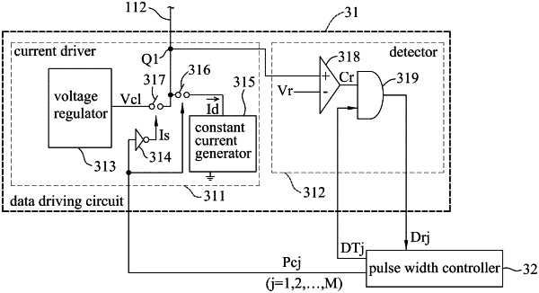
a data driver including a plurality of data driving circuits that respectively correspond to said data lines, each of said data driving circuits including
a current driver having an output terminal that is connected to said data line corresponding to said data driving circuit, receiving a pulse width control signal, and outputting one of a drive current and a first clamp voltage at said output terminal of said current driver based on the pulse width control signal, and
a detector connected to said current driver to receive a feed-in voltage related to a voltage at said output terminal of said current driver, further receiving a detection timing signal, and generating a detection signal that indicates whether any one of said LEDs connected to said data line corresponding to said data driving circuit is short circuited based on the feed-in voltage and the detection timing signal;
wherein, with respect to each of said data driving circuits, said detector is connected to said output terminal of said current driver, and receives the voltage at said output terminal of said current driver to serve as the feed-in voltage, and said current driver includes
a voltage regulator generating the first clamp voltage,
an inverter receiving the pulse width control signal, and generating an inverted control signal that is a logical complement of the pulse width control signal in logic value,
a constant current generator generating the drive current,
a first switch having a first terminal that is connected to said output terminal of said current driver, a second terminal that is connected to said constant current generator, and a control terminal that receives the pulse width control signal, said first switch, when conducting based on the pulse width control signal, permitting flow of the drive current therethrough, and
a second switch having a first terminal that is connected to said voltage regulator, a second terminal that is connected to said output terminal of said current driver, and a control terminal that is connected to said inverter to receive the inverted control signal, said second switch, when conducting based on the inverted control signal, permitting transmission of the first clamp voltage therethrough.
|
|
3. A scan-type display apparatus comprising:
a light emitting diode (LED) array having a common anode configuration, and including
a plurality of scan lines,
a plurality of data lines, and
a plurality of LEDs arranged in a matrix that has a plurality of rows respectively corresponding to said scan lines and a plurality of columns respectively corresponding to said data lines,
with respect to each of said rows, anodes of said LEDs in said row being connected to said scan line that corresponds to said row,
with respect to each of said columns, cathodes of said LEDs in said column being connected to said data line that corresponds to said column; and
a data driver including a plurality of data driving circuits that respectively corresponds to said data lines, each of said data driving circuits including
a current driver having an output terminal that is connected to said data line corresponding to said data driving circuit, receiving a pluse width control signal, and outputting one of a drive current and a first clamp voltage at said output terminal of said current driver based on the pulse width control signal, and
a detector connected to said current driver to receive a feed-in voltage related to a voltage at said output terminal of said current driver, further receiving a detection timing signal, and generating a detection signal that indicates whether any one of said LEDs connected to said data line corresponding to said data driving circuit is short circuited based on the feed-in voltage and the detection timing signal;
wherein, with respect to each of said data driving circuits, said current driver includes:
a voltage regulator generating the first clamp voltage;
an inverter receiving the pulse width control signal, and generating an inverted control signal that is a logical complement of the pulse width control signal in logic value;
a constant current generator generating the drive current;
a first switch having a first terminal that is connected to said output terminal of said current driver, a second terminal that is connected to said constant current generator, and a control terminal that receives the pulse width control signal, said first switch, when conducting based on the pulse width control signal, permitting flow of the drive current therethrough; and
a second switch having a first terminal that is connected to said voltage regulator, a second terminal that is connected to said output terminal of said current driver, and a control terminal that is connected to said inverter to receive the inverted control signal, said second switch, when conducting based on the inverted control signal, permitting transmission of the first clamp voltage therethrough from said voltage regulator to said output terminal of said current driver, and
said detector is connected to said second terminal of said first switch, and receives a voltage at said second terminal of said first switch to serve as the feed-in voltage.
|
|
20. A data driver adapted to be used in a scan-type display apparatus that includes a light emitting diode (LED) array, the LED array having a common anode configuration, and including a plurality of data lines and a plurality of LEDs, each of the LEDs being connected to a corresponding one of the data lines, said data driver comprising a plurality of data driving circuits that respectively correspond to the data lines, each of said data driving circuits including:
a current driver having an output terminal that is connected to the data line corresponding to said data driving circuit, receiving a pulse width control signal, and outputting one of a drive current and a clamp voltage at said output terminal of said current driver based on the pulse width control signal; and
a detector connected to said current driver to receive a feed-in voltage related to a voltage at said output terminal of said current driver, further receiving a detection timing signal, and generating a detection signal that indicates whether any one of the LEDs connected to the data line corresponding to said data driving circuit is short circuited based on the feed-in voltage and the detection timing signal;
wherein, with respect to each of said data driving circuits, said detector is connected to said output terminal of said current driver, and receives the voltage at said output terminal of said current driver to serve as the feed-in-voltage, and said current driver includes
a voltage regulator generating the clamp voltage,
an inverter receiving the pulse width control signal, and generating an inverted control signal that is a logical complement of the pulse width control signal in logic value,
a constant current generator generating the drive current,
a first switch having a first terminal that is connected to said output terminal of said current driver, a second terminal that is connected to said constant current generator, and a control terminal that receives the pulse width control signal, said first switch, when conducting based on the pulse width control signal, permitting flow of the drive current therethrough, and
a second switch having a first terminal that is connected to said voltage regulator, a second terminal that is connected to said output terminal of said current driver, and a control terminal that is connected to said inverter to receive the inverted control signal, said second switch, when conducting based on the inverted control signal, permitting transmission of the clamp voltage therethrough.
|