| CPC F23R 3/16 (2013.01) [F02C 7/22 (2013.01)] | 20 Claims |

|
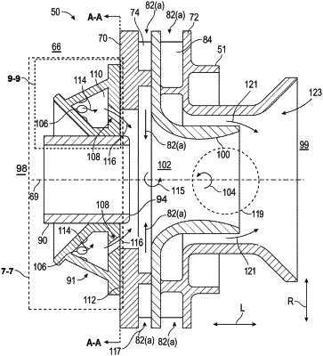
1. A swirler assembly of a combustor, the swirler assembly defining a swirler assembly centerline therethrough, the swirler assembly comprising:
a swirler including a primary swirler having a primary swirler venturi;
a swirler ferrule plate connected to an upstream side of the primary swirler and including a fuel nozzle opening extended therethrough along the swirler assembly centerline; and
a fuel nozzle disposed in the fuel nozzle opening of the swirler ferrule plate,
the swirler ferrule plate comprising:
(a) an aft wall extending radially outward from the fuel nozzle opening;
(b) an axial wall extending upstream from an upstream side of the aft wall at the fuel nozzle opening;
(c) an annular conical wall extending from a radially inward portion of the axial wall at the fuel nozzle opening, and extending radially outward upstream from the axial wall; and
(d) an annular cavity wall connecting a radially outward portion of the aft wall and an upstream end of the annular conical wall enclosing, annular cavity between the aft wall, the axial wall, the annular conical wall, and the annular cavity wall, the annular cavity wall including a plurality of inlet orifices therethrough,
wherein at least one of the aft wall and the axial wall includes at least one outlet orifice providing fluid communication between the annular cavity and the primary swirler venturi, and wherein a flow of an oxidizer through the plurality of inlet orifices into the annular cavity incurs a first pressure drop from a first pressure of a pressure plenum to a second pressure lower than the first pressure, and a flow of the oxidizer from the annular cavity through the at least one outlet orifice into the primary swirler venturi incurs a second pressure drop from the second pressure to a third pressure lower than the second pressure.
|
|
13. A method of operating a combustor of a gas turbine, the combustor comprising (i) a pressure plenum, (ii) a swirler assembly including (a) a swirler having a primary swirler with a primary swirler venturi, and (b) a swirler ferrule plate connected to the primary swirler and including a fuel nozzle opening extended therethrough, and an annular pressure drop cavity formed by an aft wall extending radially outward from the fuel nozzle opening, an axial wall extending upstream from an upstream side of the aft wall at the fuel nozzle opening, an annular conical wall extending from a radially inward portion of the axial wall at the fuel nozzle opening and extending radially outward upstream from the axial wall, and an annular cavity wall connecting a radially outward portion of the aft wall and an upstream end of the annular conical wall, the annular pressure drop cavity having a plurality of inlet orifices in fluid communication with the pressure plenum and at least one outlet orifice in fluid communication with a primary swirler venturi region, and (iii) a fuel nozzle disposed in the fuel nozzle opening of the swirler ferrule plate, the method comprising:
providing a first flow of an oxidizer to the pressure plenum, the first flow of the oxidizer having a first pressure;
providing a second flow of the oxidizer from the pressure plenum to the annular pressure drop cavity of the swirler ferrule plate via the plurality of inlet orifices of the annular pressure drop cavity, the second flow of the oxidizer inducing a first pressure drop in the flow of the oxidizer from the first pressure to a second pressure lower than the first pressure in the annular pressure drop cavity; and
providing a third flow of the oxidizer from the annular pressure drop cavity to a primary swirler venturi region via the at least one outlet orifice of the swirler ferrule plate, the third flow of the oxidizer inducing a second pressure drop in the flow of the oxidizer from the second pressure to a third pressure lower than the second pressure.
|