|
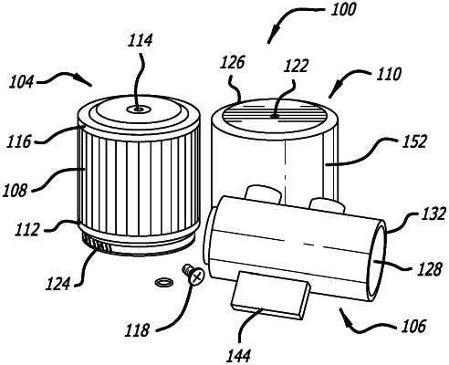
1. A crankcase breather vent assembly for an internal combustion engine, comprising: a breather vent for cleaning air being drawn into a crankcase comprised of a filter medium retained between a base and a cap; a vent base for capturing oil from blow-by gases; a bonnet extending over the breather vent for reducing oil residue buildup on nearby engine components; in the multiplicity of baffles are configured to cause blow-by gases to traverse a tortuous path through the interior cavity; the tortuous path is configured to cause oil carried by the blow-by gases to collected on the multiplicity of baffles; one or more inlets are configured to receive blow-by gases from the crankcase into the interior cavity; an outlet is configured to drain captured oil from the interior cavity to an oil sump, and wherein an outer profile of the breather vent is tapered along a longitudinal dimension of the filter medium, such that a diameter of the breather vent near the cap is greater than the diameter near the base of the breather vent, the tapering of the diameter being configured to facilitate an unrestricted air flow through the filter medium when the bonnet is installed onto the breather vent.
|
