US 11,993,677 B2
Combination mobile built-in air flow mechanism and LED kill chamber
Darrin W. Niemiec, Schaumburg, IL (US); and William J. Carlson, Schaumburg, IL (US)
Assigned to Go Fan Yourself, LLC, Schaumburg, IL (US)
Filed by Darrin W. Niemiec, Schaumburg, IL (US); and William J. Carlson, Schaumburg, IL (US)
Filed on Mar. 16, 2023, as Appl. No. 18/122,321.
Application 18/122,321 is a continuation of application No. 17/739,337, filed on May 9, 2022, granted, now 11,608,411, issued on Mar. 21, 2023.
Application 17/739,337 is a continuation in part of application No. 16/943,352, filed on Jul. 30, 2020, granted, now 11,332,573, issued on May 17, 2022.
Application 16/943,352 is a continuation in part of application No. 16/377,750, filed on Apr. 8, 2019, granted, now 11,028,223, issued on Jun. 8, 2021.
Application 16/377,750 is a continuation of application No. 16/157,874, filed on Oct. 11, 2018, granted, now 10,316,141, issued on Jun. 11, 2019.
Application 16/157,874 is a continuation in part of application No. 16/040,189, filed on Jul. 19, 2018, granted, now 10,221,857, issued on Mar. 5, 2019.
Application 16/040,189 is a continuation in part of application No. 15/589,367, filed on May 8, 2017, granted, now 10,247,191, issued on Apr. 2, 2019.
Application 15/589,367 is a continuation in part of application No. 15/471,762, filed on Mar. 28, 2017, granted, now 10,006,619, issued on Jun. 26, 2018.
Claims priority of provisional application 62/439,719, filed on Dec. 28, 2016.
Prior Publication US 2023/0220156 A1, Jul. 13, 2023
This patent is subject to a terminal disclaimer.
Int. Cl. C08G 63/672 (2006.01); C08G 81/00 (2006.01); C09K 19/38 (2006.01); E04B 9/00 (2006.01); E04B 9/02 (2006.01); F04D 25/08 (2006.01); F04D 29/54 (2006.01); F21S 8/02 (2006.01); F21S 8/06 (2006.01); F21V 29/67 (2015.01); F21V 33/00 (2006.01); F21Y 115/10 (2016.01); F24F 3/16 (2021.01); F24F 8/10 (2021.01); F24F 8/22 (2021.01); F24F 13/068 (2006.01); F24F 13/078 (2006.01); F24F 13/08 (2006.01)
CPC C08G 63/672 (2013.01) [C08G 81/00 (2013.01); C09K 19/3814 (2013.01); E04B 9/02 (2013.01); F04D 25/08 (2013.01); F04D 29/545 (2013.01); F21S 8/026 (2013.01); F21S 8/061 (2013.01); F21V 29/67 (2015.01); F21V 33/0096 (2013.01); F24F 3/16 (2013.01); F24F 13/078 (2013.01); E04B 9/006 (2013.01); F05D 2250/52 (2013.01); F21Y 2115/10 (2016.08); F24F 8/10 (2021.01); F24F 8/22 (2021.01); F24F 13/068 (2013.01); F24F 13/08 (2013.01); F24F 2221/02 (2013.01); F24F 2221/125 (2013.01); F24F 2221/14 (2013.01); Y10S 525/905 (2013.01)] 19 Claims
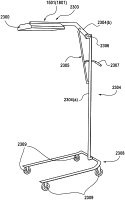
OG exemplary drawing
 
1. A mobile air purifying system, comprising:
a UV-C system having at least a vent portion and a fan portion;
an enclosure in the UV-C system wherein the enclosure defines at least an airway between the fan portion and the vent portion;
a fan positioned in the fan portion adapted to guide air to the UV-C airway;
a UV light source mounted in the UV-C airway, wherein the UV light source is a UV-C light source emitting light having a wavelength between 200 and 280 nanometers directed into the UV-C airway;
an air diversion mechanism positioned in the UV-C airway, wherein the air diversion mechanism is configured to direct air guided by the fan to a UV-C airway housing the UV light source;
a baffle is positioned in the UV-C airway to act as a barrier preventing light emitted from the UV light source from exiting the air purifying device;
the enclosure including a mount affixed to the enclosure, the mount configured to attach to a mobile support system; and
a base affixed to the mobile support system wherein the base includes a plurality of locking wheels, whereby the plurality of wheels can be locked in a first position and permitted to rotate in a second position.