| CPC B64G 1/405 (2013.01) [H01J 27/26 (2013.01); H01J 2237/0802 (2013.01); H01J 2237/317 (2013.01)] | 15 Claims |

|
1. An ion propulsion device, the device comprising:
a plurality of emission modules arranged in an emission plane of the device, each said emission module comprising an insulating support, an emission electrode arranged on the insulating support, and a tank of conductive liquid with a microfluidic channel arranged to deposit conductive liquid on the emission electrode;
an extraction electrode common to the plurality of emission modules and arranged opposite the plurality of emission modules; and
at least one control unit;
wherein:
each said emission module is configured to emit an ion beam when an electric field is applied to the conductive liquid;
the at least one control unit is configured to control an emission current of the ions emitted by application of a potential difference between at least one emission electrode of the plurality of emission electrodes and the extraction electrode;
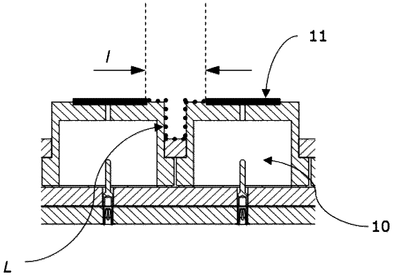
the emission electrodes of the plurality of emission modules are spaced apart from one another by a linear distance lgreater than a breakdown distance between two adjacent emission electrodes separated by an empty space, the linear distance | being less than the propagation distance of an electric leakage current by hopping conduction along the insulating support between the emission electrodes; and
a length L of an insulating support between the emission electrodes is greater than a propagation distance of an electric leakage current by hopping conduction along the insulating support between the emission electrodes, the linear distance l and the length L of the insulating support being chosen so as to | maximize the number of the plurality of emission modules in the emission plane.
|