| CPC B62M 6/75 (2013.01) [B62K 1/00 (2013.01); B62K 11/007 (2016.11); B60B 19/003 (2013.01); B60B 19/12 (2013.01)] | 5 Claims |

|
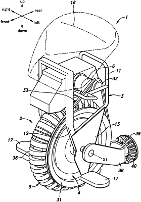
1. Drive disks arranged on either side of an annular main wheel and configured to rotate the main wheel around a central axis and an annular axis by applying a frictional force to the main wheel, each of the drive disks comprising:
a disk-shaped base rotatably supported by a frame; and
a plurality of rollers rotatably supported by an outer circumferential part of the base, inclined to each other, and coming into contact with the main wheel,
wherein the base includes a first sheet metal member and a second sheet metal member,
the first sheet metal member includes a first central part and a plurality of first arm parts extending radially outward from the first central part,
the second sheet metal member includes a second central part and a plurality of second arm parts extending radially outward from the second central part,
the first central part and the second central part are arranged coaxially with each other,
each of the rollers has a first end and a second end in a rotational axis direction thereof,
each of the first arm parts includes a first supporting part and a second supporting part arranged inside of the first supporting part in a radial direction of the base,
each of the second arm parts includes a third supporting part and a fourth supporting part arranged outside of the third supporting part in the radial direction of the base,
the first end of one of two rollers adjacent to each other is supported by the first supporting part and the second end thereof is supported by the third supporting part,
the first end of the other of the two rollers adjacent to each other is supported by the fourth supporting part and the second end thereof is supported by the second supporting part,
the first supporting part and the second supporting part are inclined to each other with a first bent part therebetween, and
the third supporting part and the fourth supporting part are inclined to each other with a second bent part therebetween.
|