| CPC B29C 48/0021 (2019.02) [B29C 48/022 (2019.02); B29C 48/07 (2019.02); B29C 48/20 (2019.02); B29C 48/252 (2019.02); B29C 48/298 (2019.02); B29C 48/92 (2019.02); B32B 5/18 (2013.01); B32B 21/047 (2013.01); B32B 21/08 (2013.01); E06B 3/7015 (2013.01); E06B 3/822 (2013.01); B29C 2948/92104 (2019.02); B29C 2948/92209 (2019.02); B29K 2027/06 (2013.01); B29K 2075/00 (2013.01); B29K 2105/043 (2013.01); B29K 2311/14 (2013.01); B32B 2250/40 (2013.01); B32B 2266/0278 (2013.01); B32B 2419/00 (2013.01); E06B 2003/7023 (2013.01)] | 8 Claims |

|
1. A hemming device for a door with a plastic-wood co-extruded skeleton, configured to perform a hemming process on doors or windows, comprising:
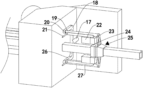
an extrusion mold and a propulsion mechanism; wherein the propulsion mechanism is arranged on a side of the extrusion mold, and another side of the extrusion mold is arranged with a converging extrusion portion; the extrusion mold is arranged with a timber port for receiving the multilayer board, and a speed sensor is arranged in the timber port; a molding port is arranged in the converging extrusion portion, and a first temperature sensor is arranged in the molding port; a molding mechanism is arranged in the converging extrusion portion; the molding mechanism comprises a suction box, a burr removing frame, and a drop box; an inner circle of the suction box defines a circle of a gas groove; a top end and a bottom end of the gas groove are each through the suction box and arranged with a suction hole; each of four corners inside the burr removing frame is arranged with a corner block; a sliding plate is arranged between two the corner blocks that are parallel; each of end surfaces of four the sliding plates facing each other is arranged with a cutter; an inner circle of the drop box defines a circle of a discharge groove; an inner wall of the discharge groove is arranged with a second temperature sensor; an inner side wall of the discharge groove near the cutter is arranged with a fixed electromagnetic plate; a magnetic slider is slidably connected to another inner side wall of the discharge groove, and the fixed electromagnetic plate and the magnetic slider are matched; a bottom on a side of the magnetic slider near the cutter is arranged with a plurality of connecting rods, and an end of each connecting rod passes through the drop box and is fixedly connected to a side wall of the sliding plate.
|