| CPC H05B 45/385 (2020.01) [H02M 1/0009 (2021.05); H02M 3/33573 (2021.05)] | 15 Claims |

|
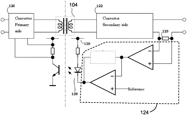
1. A flyback converter with a primary side regulation of the output current at the secondary side, the flyback converter comprising:
a transformer comprising a primary side for connection to an input supply and a secondary side for connection to a load;
a first switching circuit at the primary side adapted to allow the primary side to accumulate power from the input supply in a charging phase and to allow the secondary side to release a portion of the accumulated power to the load in a freewheeling phase;
a first sensing circuit to sense the primary side current in the charging phase; and
a second switching circuit at the primary side to allow another portion of accumulated power at the primary side to flow back to the input supply as a leakage current, in the freewheeling phase;
a second sensing circuit to derive a parameter which depends on the leakage current; and
a controller to derive a control signal (VC) for controlling the first switching circuit in dependence on the outputs of the first and second sensing circuits;
wherein the flyback converter further comprises a time detection circuit adapted to detect a time period of the freewheeling phase, and the controller is adapted to calculate a difference between the total charge released from a peak current in the primary winding for the time period of the freewheeling phase and the charge released by the leakage current in the freewheeling phase, wherein said difference is representative of the secondary side current and the controller is adapted to derive the control signal (VC) according to the difference.
|