| CPC H03H 7/0115 (2013.01) [H01F 27/24 (2013.01); H01F 27/2823 (2013.01); H01F 27/40 (2013.01)] | 3 Claims |

|
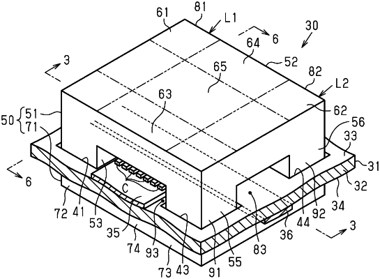
1. A filter unit, comprising:
a capacitor;
an inductor that includes a wire and a core; and
a substrate on which the capacitor is mounted, wherein
the core includes
a looped core body into which the wire is inserted, and
an opposed portion extending from the looped core body in a width direction of the substrate, to a location that is opposed to the capacitor, so that the opposed portion faces the capacitor in a thickness direction of the substrate,
the substrate includes a pattern to which the capacitor is connected, and
the pattern intersects the wire as viewed in the thickness direction of the substrate, wherein
the looped core body is one of two looped core bodies, and
the capacitor is arranged between the two looped core bodies so as to be outside of each of the two looped core bodies.
|