| CPC H03H 11/53 (2013.01) [G05F 1/46 (2013.01); G05F 1/56 (2013.01)] | 9 Claims |

|
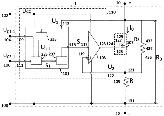
1. An electronically controllable resistor (ECR) (1) comprising: a voltage converter (101), an instrument resistor (105), and a subtractor (103), the voltage converter (101) has a first, a second, and a third inputs (109, 111, 113), the first input (109) is connected to a terminal (104) for connecting to a first control voltage source, and the third input (113) is connected to a high-potential voltage terminal (10), a first input (117) of the subtractor (103) is connected to an output (115) of the voltage converter (103), a second input (119) of the subtractor (103) is connected to a first terminal (121) of the instrument resistor (105), a second terminal of the instrument resistor (105) being connected to a low-potential terminal (12),
wherein
the second input (111) of the voltage converter (101) is connected to a terminal (106) for connecting to a second control voltage source, the ECR (1) further comprises an executive element (107), a first terminal (125) of the executive element (107) is connected to the first terminal (121) of the instrument resistor (105), a second terminal (127) of the executive element (107) is connected to an output (123) of the subtractor (103), and a third terminal (129) of the executive element (107) is connected to the high potential terminal (10), and
wherein the voltage converter (101) is adapted to multiply a voltage at the high-potential terminal (10) by a voltage at the second input (111) and to divide by a voltage at the first input (109), to produce an intermediate voltage signal at the output (115) of the voltage converter (101), whereby regulating a resistance of the ECR becomes available by the subtractor (103) in a function of the difference between the intermediate voltage signal and a voltage drop on the instrumental resistor (105) applied to the subtractor (103), the voltage drop being created by a current flowing through the instrumental resistor and the executive element.
|