| CPC H02P 21/22 (2016.02) | 2 Claims |

|
1. A control device for an electric motor, the control device comprising:
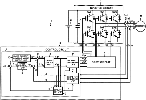
an inverter circuit that drives the electric motor with a plurality of switching elements turned on and off; and
a control circuit that converts an alternating current that flows through the electric motor to a d-axis current and a q-axis current, finds a voltage command value such that the d-axis current and the q-axis current approach a d-axis current command value and a q-axis current command value, respectively, and turns the plurality of switching elements on and off by using a drive signal in accordance with a result of comparison between the voltage command value and a carrier wave,
wherein the control circuit corrects the voltage command value by using a polarity of the alternating current during dead time in which the switching elements connected to each other in series are prohibited from being simultaneously turned on, and causes the d-axis current command value in a certain length of time before and after the alternating current reaches zero to be greater than the d-axis current command value in a length of time other than the certain length of time.
|