| CPC H02M 7/4835 (2021.05) [H02M 1/0095 (2021.05); H02M 3/33573 (2021.05); H02M 7/53871 (2013.01); H02M 5/453 (2013.01); H02M 5/458 (2013.01); H02M 5/4585 (2013.01); H02M 7/483 (2013.01); H02M 7/49 (2013.01)] | 22 Claims |
|
1. A multi-level inverter, comprising:
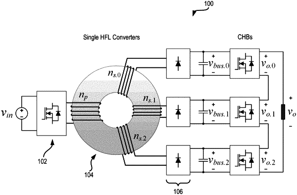
n H-bridge cells, each H-bridge cell of the n H-bridge cells configured to selectively provide at its output terminals one of: a zero voltage, a positive polarity of a voltage at its input terminals, and a negative polarity of the voltage at its input terminals, wherein the corresponding input terminals of each H-bridge cell of the n H-bridge cells is configured to be coupled to one of n DC voltage sources, wherein at least two of the n DC voltage sources have different voltage magnitudes;
m H-bridge cells, each H-bridge cell of the m H-bridge cells having a capacitor coupled in parallel with its input terminal, the each H-bridge cell of the m H-bridge cells configured to selectively provide one of: charging the capacitor from its output terminals, discharging the capacitor to its output terminals, and providing zero voltage at its output terminals, wherein the n H-bridge cells and the m H-bridge cells are connected in a cascade formation such that a voltage output of the multi-level inverter is equal to at least a sum of output voltages of the n H-bridge cells and the m H-bridge cells; and
a controller coupled with the n H-bridge cells and the m H-bridge cells configured to:
determine a first half-cycle period and a second subsequent half-cycle period of a same duration as the first half-cycle period, each of the first half-cycle period and the second half-cycle period including a set of switching instances, wherein each switching instance in the set of switching instances is determined at least in part based upon the voltage magnitudes of each of the n DC voltage sources, and
selectively control the n H-bridge cells and the m H-bridge cells at each switching instance of the set of switching instances of the first half-cycle period to generate a step-wise increasing followed by a step-wise decreasing voltage output of the multi-level inverter and selectively control the n H-bridge cells and the m H-bridge cells at each switching instance of the set of switching instances of the second half-cycle period to generate a step-wise decreasing followed by a step-wise increasing voltage output of the multi-level inverter.
|