| CPC H02M 3/158 (2013.01) [H02M 1/0009 (2021.05); H02M 1/0058 (2021.05); H02M 3/07 (2013.01)] | 30 Claims |

|
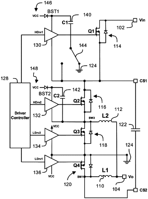
1. A power converter comprising:
an input configured to receive an input voltage;
an output configured to output an output voltage that is different than the input voltage;
a first inductor;
a second inductor;
a first switch;
a second switch;
a third switch, wherein the second switch and the third switch are configured to control current through the second inductor;
a fourth switch, wherein the first switch and the fourth switch are configured to control current through the first inductor;
an AC coupling capacitor that is coupled between the first power switch and the first inductor;
a fifth switch having a first state that couples the AC coupling capacitor to a discharge path to at least partially discharge the AC coupling capacitor, the fifth switch having a second state that decouples the AC coupling capacitor from the discharge path; and
a driver configured to operate the first, second, third, fourth, and fifth switches to change the input voltage to provide the output voltage;
wherein the driver is configured to provide:
a first state of operation wherein:
the first switch is on;
the second switch is on;
the third switch is off;
the fourth switch is off; and
the fifth switch is off;
a second state of operation wherein:
the first switch is on;
the second switch is off;
the third switch is on;
the fourth switch is off; and
the fifth switch is off;
a third state of operation wherein:
the first switch is on;
the second switch is on;
the third switch is off;
the fourth switch is off; and
the fifth switch is off; and
a fourth state of operation wherein:
the first power switch is off;
the second power switch is on;
the third power switch is off;
the fourth power switch is on; and
the fifth switch is on.
|