| CPC H02M 1/0025 (2021.05) [H02M 3/1586 (2021.05)] | 18 Claims |

|
1. A multi-rail power converter assembly comprising:
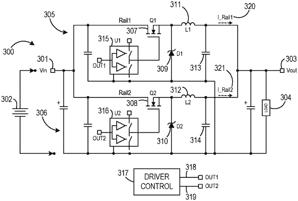
a first power converter comprising a first rail and configured to receive an input voltage and to output a first rail current on the first rail based on the input voltage;
a second power converter comprising a second rail, the second power converter interleaved with the first power converter and configured to receive the input voltage and to output a second rail current based on the input voltage; and
a control driver circuit comprising:
a first control output configured to output a first control signal to control power conversion of the input voltage in the first power converter to generate the first rail current;
a second control output configured to output a second control signal to control power conversion of the input voltage in the second power converter to generate the second rail current;
a first pulse-width modulation (PWM) generator configured to receive a compensator control signal and to generate the first control signal based on the compensator control signal;
a second PWM generator configured to receive a first modified compensator control signal and to generate the second control signal based on the first modified compensator control signal; and
a current balancing assembly configured to receive the compensator control signal and to generate the first modified compensator control signal;
wherein the control driver circuit is configured to generate the first modified compensator control signal based on an average of the first rail current and the second rail current; and
wherein the current balancing assembly comprises:
an averaging circuit configured to generate an average current signal based on the first rail current and the second rail current;
a reference comparison circuit configured to generate a current compensation signal based on a comparison of the average current signal with the second rail current; and
a compensator control signal modification circuit configured to generate the first modified compensator control signal based on the compensator control signal and the current compensation signal.
|