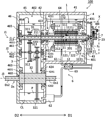
| CPC H02K 5/225 (2013.01) [H02K 11/33 (2016.01); H02K 2203/09 (2013.01); H02K 2213/03 (2013.01)] | 5 Claims |

|
1. A motor, comprising:
a shaft extending in an axial direction along a rotation axis parallel to a horizontal direction;
a rotor supported by the shaft and rotatable together with the shaft;
a stator disposed radially outward of the rotor;
a housing that accommodates the rotor and the stator, wherein the housing further includes:
a plate portion having conductivity and expanding in a radial direction of the shaft, and
a cover member disposed in one axial end surface of the plate portion; and
an electrical discharging device including a conductive member in contact with a radially outer surface of the shaft,
wherein the conductive member is in contact with a region of the radially outer surface of the shaft, the region facing any one of a vertically upper side, a vertically obliquely upper side, and a horizontal direction when viewed from the axial direction,
wherein, when viewed from the axial direction, the electrical discharging device is disposed on any one of:
one side and an other side in a direction perpendicular to the axial direction and parallel to the horizontal direction with respect to a contact portion between the shaft and the conductive member; and
a vertically upper side with respect to the contact portion,
wherein, when viewed from the axial direction, the electrical discharging device is further disposed on any one of:
one side and an other side in the parallel direction with respect to the rotation axis; and
a vertically obliquely upper side with respect to the rotation axis,
wherein an opening through which the shaft is inserted is disposed in the plate portion,
wherein the electrical discharging device is accommodated in an accommodation space surrounded by the plate portion and the cover member,
wherein the plate portion is disposed on one axial side with respect to the stator,
wherein the accommodation space includes a lower space having a predetermined size disposed vertically downward from the opening,
wherein the cover member includes:
a first cover portion that covers the electrical discharging device; and
a second cover portion that is disposed radially outward of the first cover portion,
wherein the second cover portion is disposed on the other axial side with respect to the first cover portion, and
wherein the lower space is disposed between the plate portion and the second cover portion.
|