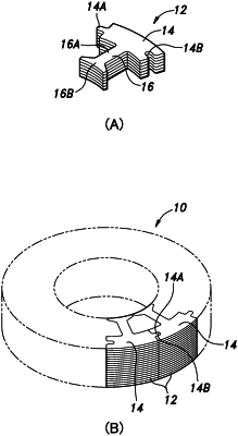
| CPC H02K 15/02 (2013.01) [B21D 28/02 (2013.01); H01F 41/0233 (2013.01); B32B 38/0004 (2013.01)] | 7 Claims |

|
1. A manufacturing apparatus for a laminated iron core formed by stacking and adhesively bonding iron core laminae, each iron core lamina formed by punching an intermittently conveyed sheet steel strip into a predetermined shape, the manufacturing apparatus comprising:
a first punch and a first die configured to punch a part of an outer shape of each iron core lamina in the sheet steel strip;
an adhesive applicator configured to apply an adhesive agent on an adhesive agent application region including a portion defined in the sheet steel strip by punching by the first punch and the first die; and
a second punch and a second die configured to punch the outer shape of each iron core lamina other than the part punched by the first punch and the first die from the sheet steel strip, the second die being provided with a blade portion having a same shape as the outer shape of each iron core lamina other than the part punched by the first punch and the first die,
wherein the second die has a die hole, the die hole being provided, in a portion thereof corresponding to the part of the outer shape of the iron core lamina punched by the first punch and the first die, with a recess for defining a space between the part of the outer shape punched by the first punch and the first die and the second die as seen in a plan view from above the second die, the recess forming a non-blade portion of the second die,
the second die is arranged below the second punch,
the manufacturing apparatus further comprises a squeeze ring arranged below the second die to hold the iron core laminae punched by the second punch and the second die in a stacked state, and
the squeeze ring has a squeeze hole, the squeeze hole being provided, in a portion thereof corresponding to the part of the outer shape of each iron core lamina punched by the first punch and the first die, with a recess for defining a space between the part of the outer shape punched by the first punch and the first die and the squeeze ring as seen in a plan view from above the squeeze ring.
|