| CPC H01M 50/1245 (2021.01) [H01M 50/102 (2021.01); H01M 50/124 (2021.01); H01M 50/103 (2021.01); H01M 50/136 (2021.01); H01M 2220/20 (2013.01)] | 19 Claims |

|
1. An energy storage device (1000) comprising an external cladding film (200) and a housing (10); the external cladding film (200) comprising a main body and a glued layer coated on the main body; wherein the housing (10) comprises a bottom plate (13), two face plates (14) opposite to each other, and two side plates (11) opposite to each other; the bottom plate (13) is fixedly connected to bottom sides of the two side plates (11); the two face plates are fixedly connected between the two side plates (11) and are both fixedly connected to the bottom plate (13); the external cladding film (200) comprises two side film sections (S1), a bottom film section (S2), a first face film section (S31) and a second face film section (S32); the two side film sections (S1) are located at opposite ends of the external cladding film (200) and cover outside surfaces of the two side plates (11); the bottom film section (S2) is connected between the two side film sections (S1) and covers an outside surface of the bottom plate (13); the first face film section (S31) and the second face film section (S32) are located at opposite ends of the bottom film section (S2), and are both connected between the two side film sections (S1), and cover outside surfaces of the two face plates (14) respectively;
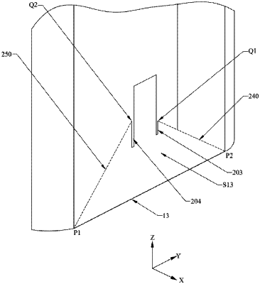
wherein each side film section (S1) defines a first cut groove (203a, 203b) and a second cut groove (204a, 204b) spaced from the first cut groove (203a, 203b); the first cut groove (203a, 203b) and the second cut groove (204a, 204b) both penetrate through the side film section (S1) along a thickness direction of the side film section (S1), and penetrate through an outer edge of the side film section (S1); a bottom surface of the first cut groove (203a, 203b) and a bottom surface of the second cut groove (204a, 204b) are both spaced from inner edges of the side film sections (S1); the first cut grooves (203a, 203b) of the two side film sections (S1) are located at opposite sides of the bottom film section (S2); the second cut grooves (204a, 204b) of the two side film sections (S1) are located at opposite sides of the bottom film section (S2) and located at one side of the first cut groove (203a, 203b) away from the first face film section (S31);
wherein each side film section (S1) comprises a first oblique crease (240, 270a) and a second oblique crease (250, 270b); the first oblique crease (240, 270a) is located at one side of the first cut groove (203a, 203b) away from the second cut groove (204a, 204b); the first oblique crease (240, 270a) comprises a first fixed end (P1) and a first free end (Q1); the first fixed end (P1) is an intersection of the side film section (S1), the first face film section (S31) and the bottom film section (S2); the first free end (Q1) intersects with a side surface of the first cut groove (203a, 203b); a distance between the first free end (Q1) and the bottom surface of the first cut groove (203a, 203b) is greater than 0;
wherein the second oblique crease (250, 270b) is located at one side of the second cut groove (204a, 204b) away from the first cut groove (203a, 203b); the second oblique crease (250, 270b) comprises a second fixed end (P2) and a second free end (Q2); the second fixed end (P2) is an intersection of the side film section (S1), the second face film section (S32) and the bottom film section (S2); the second free end (Q2) intersects with a side surface of the second cut groove (204a, 204b); a distance between the second free end (Q2) and the bottom surface of the second cut groove (204a, 204b) is greater than 0.
|