| CPC H01L 24/05 (2013.01) [H01L 23/3107 (2013.01); H01L 23/49513 (2013.01); H01L 23/4952 (2013.01); H01L 23/49524 (2013.01); H01L 23/49562 (2013.01); H01L 24/03 (2013.01); H01L 2224/02166 (2013.01); H01L 2224/02181 (2013.01); H01L 2224/02185 (2013.01); H01L 2224/0219 (2013.01); H01L 2224/03013 (2013.01); H01L 2224/03848 (2013.01); H01L 2924/07025 (2013.01)] | 16 Claims |

|
1. A semiconductor device comprising:
a semiconductor element that includes an element main body having an element main surface facing one side in a thickness direction, and a first electrode arranged on the element main surface;
a first insulating layer that is arranged over a peripheral edge portion of the first electrode and the element main surface and includes a first annular portion formed in an annular shape when viewed in the thickness direction; and
a second insulating layer that is laminated on the first insulating layer, is made of a resin material, and includes a second annular portion overlapping with the first annular portion when viewed in the thickness direction,
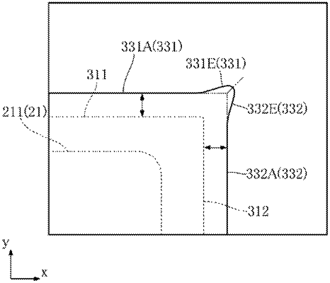
wherein the first annular portion includes a first outer end boundary line extending in a first direction orthogonal to the thickness direction, and a second outer end boundary line connected to the first outer end boundary line and extending in a second direction orthogonal to both the thickness direction and the first direction,
wherein the second annular portion includes a third outer end boundary line located outside the first outer end boundary line in the second direction and a fourth outer end boundary line located outside the second outer end boundary line in the first direction, when viewed in the thickness direction,
wherein the third outer end boundary line includes:
a center portion in the first direction; and
an end portion near the fourth outer end boundary line;
wherein the end portion of the third outer end boundary line protrudes outward in the second direction as compared with the center portion of the third outer end boundary line,
wherein the fourth outer end boundary line includes:
a center portion in the second direction; and
an end portion near the third outer end boundary line;
wherein the end portion of the fourth outer end boundary line protrudes outward in the first direction as compared with the center portion of the fourth outer end boundary line,
wherein the first annular portion includes a first inner end boundary line located inside the first outer end boundary line in the second direction and a second inner end boundary line connected to the first inner end boundary line and located inside the second outer end boundary line in the first direction, when viewed in the thickness direction, and
wherein the second annular portion includes a third inner end boundary line located inside the first inner end boundary line in the second direction and a fourth inner end boundary line connected to the third inner end boundary line and located inside the second inner end boundary line in the first direction, when viewed in the thickness direction.
|