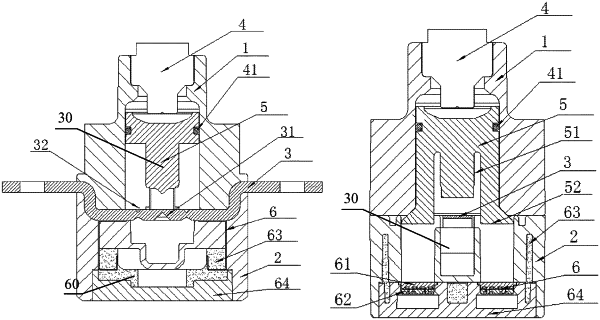
| CPC H01H 85/05 (2013.01) [H01H 85/143 (2013.01); H01H 85/165 (2013.01); H01H 85/38 (2013.01)] | 27 Claims |

|
1. An excitation fuse with a conductor and a fusant being sequentially broken, the excitation fuse comprising a housing and a cavity in the housing, wherein at least one conductor is inserted in the housing and the cavity and configured to have two ends connected with an external circuit; at least one fusant is provided in parallel on each of the at least one conductor; an excitation device and a breaking device are mounted in the cavity at one side of the each conductor; the excitation device is configured to receive an external excitation signal to act to drive the breaking device to sequentially form at least one fracture on the each conductor and the each fusant respectively; and the at least one fracture on the each conductor is connected in parallel with the each fusant,
wherein at least one set of force applying assemblies is provided on the fusant located in the housing, and the force applying assembly is configured to be driven by the breaking device, to break the fusant to form the fracture; and
the force applying assembly comprises at least one push rod and at least one guide rod, the arc extinguishing medium is filled around the push rod and the guide rod, and the fusant is located between the push rod and the guide rod; one end of the push rod penetrates through and extends out of the arc extinguishing chamber; one end of the guide rod displaces into a reserved displacement space in the arc extinguishing chamber; a blocking structure configured to prevent leakage of the arc extinguishing medium is provided between the push rod and the guide rod and a wall of the arc extinguishing chamber; after the breaking device breaks the conductor, the breaking device drives the push rod and the guide rod to displace in a linear manner to break the fusant, where two segments of the broken fusant are a cathode and an anode respectively, with an arc path between the cathode and the anode; and the cathode and/or the anode remains in the arc extinguishing medium, and at least a part of the arc path is in the arc extinguishing medium.
|