| CPC H01H 21/22 (2013.01) [B25F 5/02 (2013.01); H01H 3/20 (2013.01); H01H 9/20 (2013.01); H01H 21/04 (2013.01)] | 7 Claims |

|
1. A switch assembly, comprising:
a housing, extending along a longitudinal axis;
a main control switch, housed within the housing;
a locking switch, slidably connected to the housing and movable between a locking position and a releasing position, wherein an angle of 0° is formed between a sliding direction of the locking switch and the longitudinal axis; and
a start switch, rotatably connected with the housing by a pivot, wherein
the locking switch is in contact with the start switch when the locking switch is in the locking position and the start switch is in a locked state, and the locking switch is disengaged from the start switch when the locking switch is in the releasing position and the start switch is in a released state;
wherein the locking switch comprises:
a first operating part, protruding from the housing;
an abutting part, housed within the housing; and
a main body part connecting the first operating part and the abutting part,
wherein the abutting part extends from the first operating part toward the start switch, and the abutting part is in contact with the start switch when the locking switch is in the locking position;
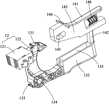
wherein the start switch comprises:
a contact part, disposed within the housing; and
a second operating part, protruding from the housing,
wherein the contact part is in contact with the main control switch, and the second operating part comprises an end surface, wherein the abutting part is in contact with the end surface of the second operating part when the locking switch is in the locking position, and the abutting part is disengaged from the end surface of the second operating part when the locking switch is in the releasing position, and wherein the second operating part is provided with a containing cavity for containing the abutting part;
wherein one end of the main body part is provided with a sliding groove which extends in a direction parallel to the longitudinal axis, and a convex column is arranged on an inside wall of the housing and penetrates through the sliding groove;
wherein the main body part is capable of moving in a direction parallel to the longitudinal axis with respect to the housing, then synchronously drive the abutting part to move in a direction parallel to the longitudinal axis while the first operating part is pushed to move in a direction parallel to the longitudinal axis;
wherein the containing cavity is located among a first side wall, a second side wall and a third side wall;
wherein after the second operating part is operated and the locking switch is in the releasing position, the abutting part protrudes into and is housed within the containing cavity; and
wherein the third side wall at a rear end of the containing cavity is configured to hold the locking switch in the releasing position when a continuous pressure is applied to the second operating part to keep the main control switch being turned on.
|