| CPC H01G 9/145 (2013.01) [H01G 9/02 (2013.01); H01G 9/035 (2013.01); H01G 9/048 (2013.01); H01G 9/10 (2013.01)] | 12 Claims |

|
1. A capacitor comprising:
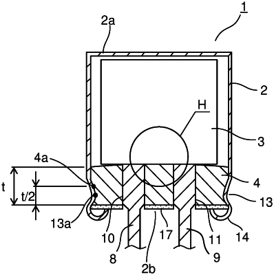
a capacitor element holding a predetermined solution between an anode foil and a cathode foil that are wound up with a separator in between;
a body case for housing the capacitor element; and
a sealing member for sealing the body case,
wherein
a part of the separator bends to make contact, at a plurality of points or over an area, with a face of the sealing member facing the capacitor element so as to rest on said face, while
the solution contains, dissolved in a lipophilic solvent, a sealing member deterioration preventing agent that solidifies by oxidation,
the solution is supplied through the separator to the sealing member and permeates the sealing member, so that a coating resulting from the sealing member deterioration preventing agent solidifying coats an outer face of the sealing member, leaving the solution present in a part of the sealing member closer to the capacitor element than the coating.
|